[0030] In an alternate embodiment distinct femoral sub-components and tibial sub-components may be interconnected with flexible
interconnection means such as one or more spring elements, wires, flanges or hinges to enable bending the construct to facilitate passage through a
small incision when the sub-components are joined outside the joint space (i.e. when preassembled). Alternatively, the sub-components can be inserted through the incision individually and the flexible
interconnection means used to join the subcomponents within the joint space. After the sub-components have been joined with the flexible interconnection means and after placement in the
joint cavity, the flexible interconnection means also assist in repositioning the components onto the kinematically prepared bone surfaces. Flexible interconnection means may be made from a suitable
alloy to include, but are not limited to, NP35N or Nitinol, or polymers to include, but limited to,
polyethylene or Gore-Tex.
[0032] The femoral sub-components are accurately orientated to one another after placement in the
joint cavity before or after interconnecting the individual sub-components with the flexible interconnecting means. Likewise, the tibial sub-components are accurately orientated to one another in the same manner. In both cases, the size of each component or sub-component passed into the joint is significantly reduced compared to conventional components enabling completion of the procedure through a smaller and less traumatic
exposure. The sub-components may be aligned and or joined one to another within the confines of the joint, such pieces being properly orientated, but not joined within the
joint cavity. Alternatively, the independent femoral sub-components may be properly orientated and joined within the joint cavity. Likewise, the tibial component may be distinct pieces to cover the medial and lateral tibial plateaus, such pieces being, properly orientated, but not joined within the joint cavity. Alternatively, the distinct tibial pieces may be properly orientated and joined within the joint cavity. The patellar component is generally of a size, i.e. from X to Y, that can be placed through minimally invasive incisions as a unitary bearing,
fixed bearing or
mobile bearing component. In one aspect of the present invention, the
articular surface of the patellar component may comprise independent, distinct pieces for the lateral
facet and medial facets which are properly orientated, but not joined within the joint cavity. In yet another aspect of the present invention, the independent patellar pieces may be properly orientated and joined within the joint cavity. In still another aspect of the present invention, the
femoral component may be flexible or include flexible sub-components.
[0036] Femoral sub-components conform to the shape of the kinematically prepare condyles and trochlea. The interfaces between femoral sub-components are partially constrained. These interfaces are unconstrained in angulation generally in a
sagittal plane to allow the sub-components to conform to the trochlear and condylar resections. These interfaces are constrained in angulation generally in a
transverse plane, in orthogonal and axial translation and in
axial rotation to provide a smooth transition from one sub-component to an adjacent sub-component. A smooth transition provides uniform support for the
mating tibial or patellar component. Alternatively, the interfaces between the femoral sub-components are unconstrained in angulation and constrained in other
degrees of freedom to allow the femoral component to conform to the resected
femoral condyles and to vary the anteroposterior
divergence of the
condyle sub-components with a similar
divergence in tibial sub-components. Alternatively, the interfaces between the femoral sub-components are fully constrained. Likewise, tibial sub-components are properly aligned with one another to ensure proper tracking of the femoral, tibial and patellar components.
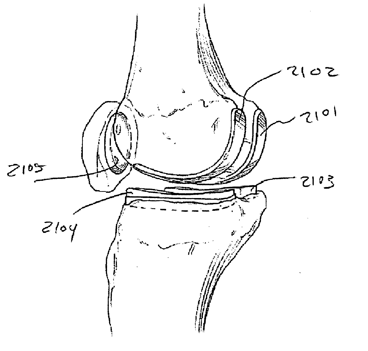
[0040] It may be advantageous to partially assemble the femoral
implant outside the joint cavity, for example passing the medial condylar sub-component into the joint cavity then assembling the lateral condylar sub-component to the trochlear sub-component and passing the
assembly into the joint cavity to engage the medial condylar sub-component. The trochlear to medial condylar sub-component interface is then assembled and the femoral component secured to the
femur. Alternatively, the medial condylar sub-component is placed into the joint cavity and secured to the
femur, and then the trochlear and lateral condylar sub-components are assembled and passed into the joint cavity to engage the medial condylar sub-component and secured to the
femur. Alternatively, the medial and lateral condylar sub-components are individually passed into the joint cavity and held in position with a bracket connected to both sub-components. The medial and lateral condylar sub-components are secured to the femur, the bracket is removed and the trochlear sub-component is passed into the joint cavity to engage the medial and lateral sub-components, assembled and secured to the femur.
[0044] The placing, guiding and securing of three sub-components of a modular femoral component with
tethering means in accordance with the present invention will now be described. A
tethering means is attached to the medial condylar sub-component and a second tethering means is attached to the lateral condylar sub-compartment. Each condylar sub-component is individually passed through the small or minimally invasive incision, positioned and secured to the femur; leaving its respective tethering means extending out of the incision. Each tethering means is passed through its corresponding through hole in the trochlear sub-component and the trochlear sub-component is advanced over the tethering means which guide the trochlear sub-component through the minimally invasive incision and into the joint cavity. The tethering means further guide the trochlear sub-component to join with the medial and lateral condylar sub-components. A tensioner is attached to each tethering means and applies a compressive force to the trochlear sub-component thereby joining or engaging the femoral sub-components. Each tethering means is then secured to the trochlear sub-component and excess tether trimmed. This aspect of the present invention enables the placement of
implant sub-components into the joint cavity through a small or minimally invasive incision, joining of such sub-components within the confines of the joint cavity,
assembly of such sub-components within the confines of the joint cavity and securing such sub-components to one another.

