Optical Signal Amplifying Triode And Optical Signal Transfer Method, Optical Signal Relay Device, And Optical Signal Storage Device Using The Same

a technology of optical signal and relay device, which is applied in multiplex communication, pulse technique, instruments, etc., can solve the problems of limited signal processing speed, weak temperature and vibration resistance, and strict setting conditions, so as to reduce the cross-gain modulation response time and reduce the gain of the optical signal. , the effect of reducing or increasing the gain of the optical signal

Active Publication Date: 2006-01-12
JAPAN SCI & TECH CORP
View PDF8 Cites 17 Cited by
  • Summary
  • Abstract
  • Description
  • Claims
  • Application Information

AI Technical Summary

Benefits of technology

[0055] Also, preferably either or each of the first gain control optical amplifier and the second gain control optical amplifier comprises an optical amplifier formed of a light transmitting medium in which a three-level or four-level energy level system is arranged by the doping of a rare earth element. Since such an optical amplifier is slow in the cross-gain modulation response time, the signal component of the optical signal will be smoothed and the lowering or rising of the gain thereof can be detected readily.
[0056] Preferably, this aspect of the invention provides the optical signal storage device, wherein the optical signal gain control means comprises: an optical operational controller, which controls the gain of the control light supplied to the main optical signal amplifying triode unit based on the increase / decrease of the gain of the optical signal fed back by the optical feedback transmission path in order to maintain fixed the gain of the optical signal that is circulated. With this arrangement, since the optical signal that is output from the main optical signal amplifying triode unit is amplified by the all-optical operational controller based on the decrease of the gain of the optical signal that is fed back and attenuation of the optical signal due to circulation is thereby prevented, the gain of the optical signal is kept substantially fixed.

Problems solved by technology

However, a functional (signal amplification) element, which, for example, corresponds to a triode transistor in electronics, that is, an optical functional element that performs signal amplification of optical signals by direct control by other optical signals has not been realized as of yet.
A limit is thus placed in the speed of signal processing due to the inability to directly control light by light.
In this regard, the devices described in Document 1 or Document 2 are simply devices that switch light, in other words, gate switching devices that make use of wavelength conversion by Mach-Zehnder optical interferometry, and these devices had problems of being weak against temperature change and vibration and being strict in terms of setting conditions.
Such conventional arts do not disclose anything in regard to arranging an optical signal amplifying triode, which, like a transistor in an electronic circuit, is equipped with a function of using input light as control light to obtain signal-amplified output light.
Thus, an adequate response speed could not be obtained.
Also besides the above-described routing processor, since a wavelength converter, for performing wavelength conversion in accordance with the wavelength of the transmission path (wavelength bus) of the transfer destination, is equipped, and such a wavelength converter is disposed in addition to the routing processor, the device became large and in some cases, especially when a mechanically operated reflecting mirror switch is used, reliability could not be obtained.
However, with this conventional optical memory device, the storage time of an optical signal is only determined in advance by the delay time corresponding to the propagation time in the optical waveguide means among optical waveguide means 105 to 108 through which the optical signal is made to propagate and the optical signal thus cannot be taken out at a desired timing.
The degree of freedom of optical signal processing was thus limited and lowering of signal processing efficiency could not be avoided.

Method used


Image

  • Optical Signal Amplifying Triode And Optical Signal Transfer Method, Optical Signal Relay Device, And Optical Signal Storage Device Using The Same
  • Optical Signal Amplifying Triode And Optical Signal Transfer Method, Optical Signal Relay Device, And Optical Signal Storage Device Using The Same
  • Optical Signal Amplifying Triode And Optical Signal Transfer Method, Optical Signal Relay Device, And Optical Signal Storage Device Using The Same

Examples


Embodiment Construction

[0097] Embodiments of this invention shall now be described in detail with reference to the drawings.

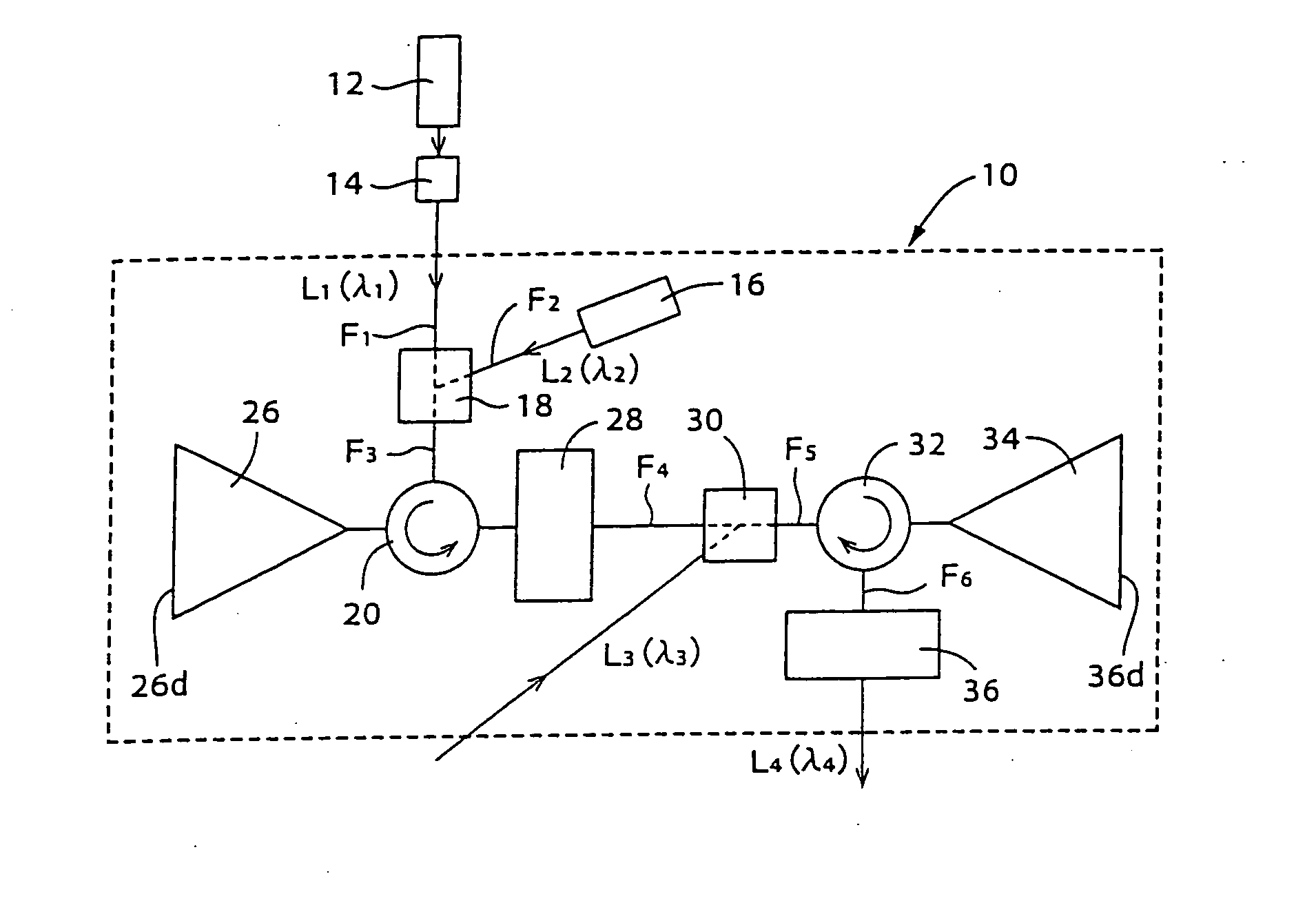
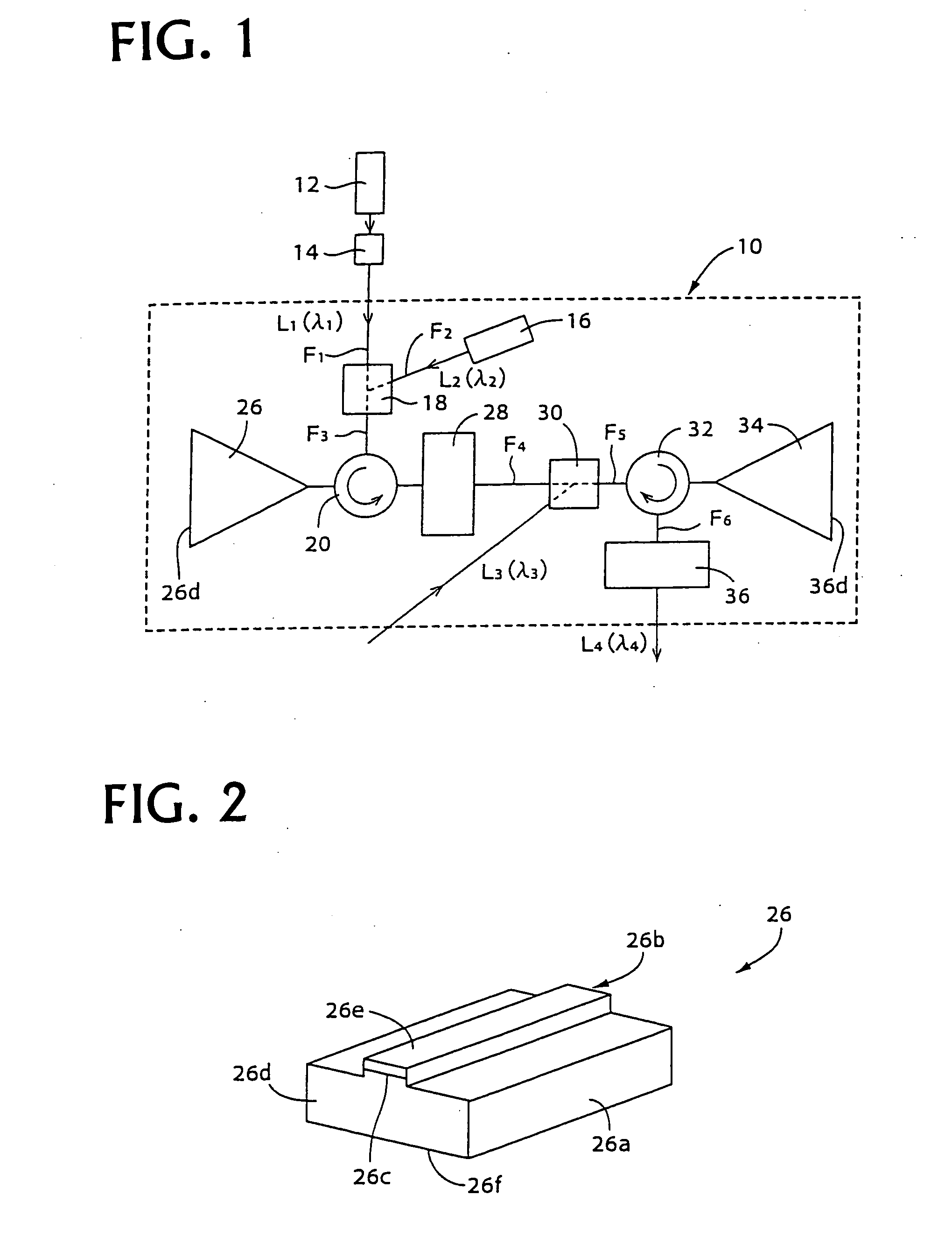
[0098]FIG. 1 through FIG. 15 show embodiments related to an optical signal amplifying triode, and FIG. 1 shows an optical signal amplifying triode 10 of one of the embodiments.

[0099] In FIG. 1, a first laser light source 12 outputs a first laser light (first input light) L1 of a first wavelength λ1 of, for example, 1555 nm, and this light is propagated via an optical fiber F1 that is provided with a first optical modulator 14. A second laser light source 16 continuously outputs a second laser light (second input light) L2 of a second wavelength λ2 of, for example, 1548 nm at a fixed intensity, and this light is propagated via a second optical fiber F2. A wavelength variable semiconductor laser is used for example as the first laser light source 12, and a semiconductor laser of a single wavelength is used for example as the second laser light source 16. The first optical modulator 1...


PUM

PropertyMeasurementUnit
first wavelength λ1aaaaaaaaaa
second wavelength λ2aaaaaaaaaa
optical path lengthaaaaaaaaaa

Abstract

When in an optical signal amplifying triode 10, light of a second wavelength λ2, selected from among light from a first optical amplifier 26, into which a first input light L1 of a first wavelength λ1 and a second input light L2 of second wavelength λ2 have been input, and a third input light (control light) L3of a third wavelength λ3 are input into a second optical amplifier 34, an output light L4 of the third wavelength λ3, selected from among the light output from the second optical amplifier 34, is light that is modulated in response to the intensity variation of one or both of the first input light L1 of the first wavelength λ1 and the third input light L3 of the third wavelength λ3 and is an amplified signal, with which the signal gain with respect to the third input light (control light) L3 of the third wavelength λ3 is of a magnitude of 2 or more. An optical signal amplifying triode 10, which can directly perform an optical signal amplification process using control input light, can thus be provided.

Description

TECHNICAL FIELD [0001] This invention concerns (a) an optical signal amplifying triode that amplifies, controls, or switches optical signals, particularly an optical signal amplifier favorable for optical communication, optical image processing, optical computers, optical measurements, optical integrated circuits and other optoelectronic applications enabling advanced information processing, (b) an optical signal transfer method and an optical signal relay device for transferring optical signals, which have been propagated via an optical fiber or other predetermined transmission path, to other transmission paths indicated by routing information included in the optical signals, and (c) an optical signal storage device that stores optical signals, which have been propagated via an optical fiber or other predetermined transmission path, and enables the optical signals to be taken out at any arbitrary time. BACKGROUND ART [0002] Wide deployment of moving image communication, video distr...

Claims


Application Information

Patent Timeline
Patent Type & Authority Applications(United States)
IPC IPC(8): G02B6/26H01S3/00G02F2/00G02F3/00H04J14/02
CPCB82Y20/00H04J14/0267G02F2/004G02F3/00G02F2002/006G02F2203/585G02F2203/70H04J14/02H04J14/0201H04J14/0204H04J14/0205H04J14/0212H04J14/0213H04J14/0221H04J14/0246G02F1/01708G02F2/006
Inventor MAEDA, YOSHINOBU
Owner JAPAN SCI & TECH CORP
Why Eureka
Try Eureka