Percutaneous aortic valve

a technology of aortic valve and percutaneous aortic valve, applied in the field of prosthetic valves, can solve the problems of reduced heart blood output, blood leakage back into the heart, chest pain,

Inactive Publication Date: 2006-01-12
REX MEDICAL LP
View PDF28 Cites 330 Cited by
  • Summary
  • Abstract
  • Description
  • Claims
  • Application Information

AI Technical Summary

Problems solved by technology

If the aortic valve doesn't close properly after the heart pumps the blood through the valve into the aorta, blood will leak back into the heart.
This oxygenated back flow of blood causes the heart to work harder and faster, thereby initially causing chest pain, fatigue, and reduced blood output from the heart, which over time can result in cardiomyopathy.
Additionally, when the aortic valve is defective for a period of time, it oftentimes leads to mitral valve damage because the retrograde inflow of blood applies pressure against the mitral valve, preventing it from closing properly.
In either instance, valve malfunction can leads to cardiomyopathy which is a disease of the heart muscle which if left untreated can lead to heart failure and death or post stenotic dilatation of the aorta which can lead to aneurysm.
If a defective heart valve cannot be surgically repaired, it may need to be removed and replaced with a replacement valve.
This open surgery is quite traumatic because it requires a full sternotomy, namely cracking the patient's ribs and creating a chest incision extending almost along the entire length of the chest.
The problems and risks inherent with the heart lung machine are well documented.
These include the risk of infection, trauma to the body as a result of the blood exchange, and the risk of brain damage or stroke.
It is also been found that patients who undergo open heart surgery may suffer from permanent neurological lapses.
This cross clamping can dislodge plaque inside the vessel, potentially sending it through the bloodstream to the brain and causing stroke.
Moreover, open heart surgery, being a highly invasive procedure, requires a long patient recovery time.
The long patient recovery time, the use of the heart lung machine, and the requirement for additional hospital staff, e.g. machine technicians, all add to the costs of the surgical procedure.
However, these approaches still require cracking and / or retracting ribs and are surgically difficult not only due to the limited access and maneuverability of the instrumentation, but due to limited visibility.
Additionally, the heart may need to be manipulated to provide proper access, potentially causing additional trauma.
For these reasons, such minimally invasive approaches have found only limited applications in bypass procedures and to the inventors' knowledge have not been successfully used for aortic valve replacement surgery.
To the inventors' knowledge, this form of endoscopic surgery is not currently being utilized, most likely because 1) access is limited; 2) the ability to manipulate the tissue and valve through small tubes is difficult; 3) visibility is limited; 4) and the small instrumentation needed for the procedure is limited.
The problem with this endoscopic approach is compounded by the fact that the valve is sutured to the valve annulus.
As can be appreciated, manipulating a suturing instrument through small tubes, with limited maneuverability and restricted visibility is quite difficult.
Therefore, to date, no surgical method is effective in avoiding the aforementioned disadvantages of open heart valve surgery.

Method used


Image

  • Percutaneous aortic valve
  • Percutaneous aortic valve
  • Percutaneous aortic valve

Examples


first embodiment

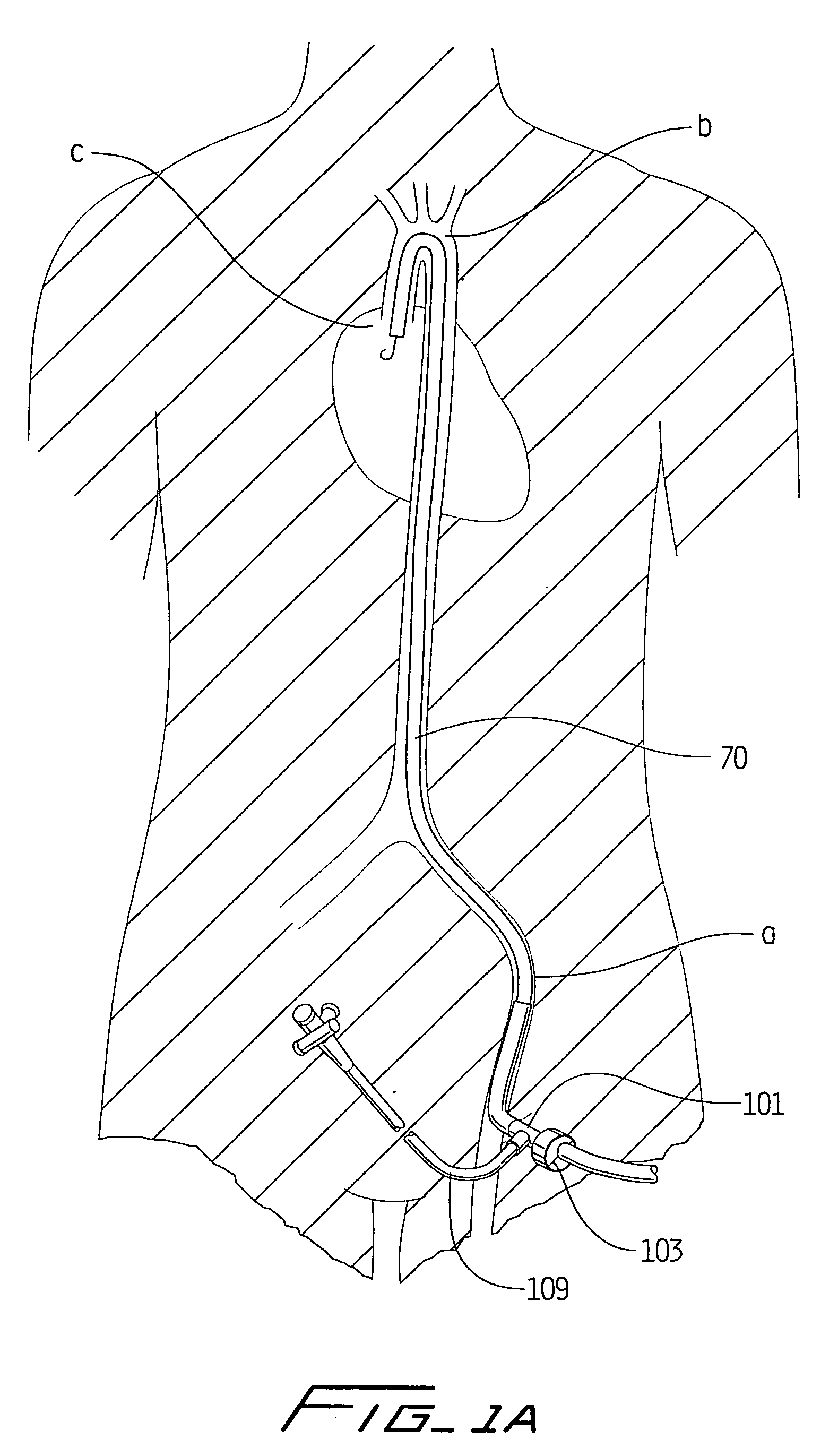
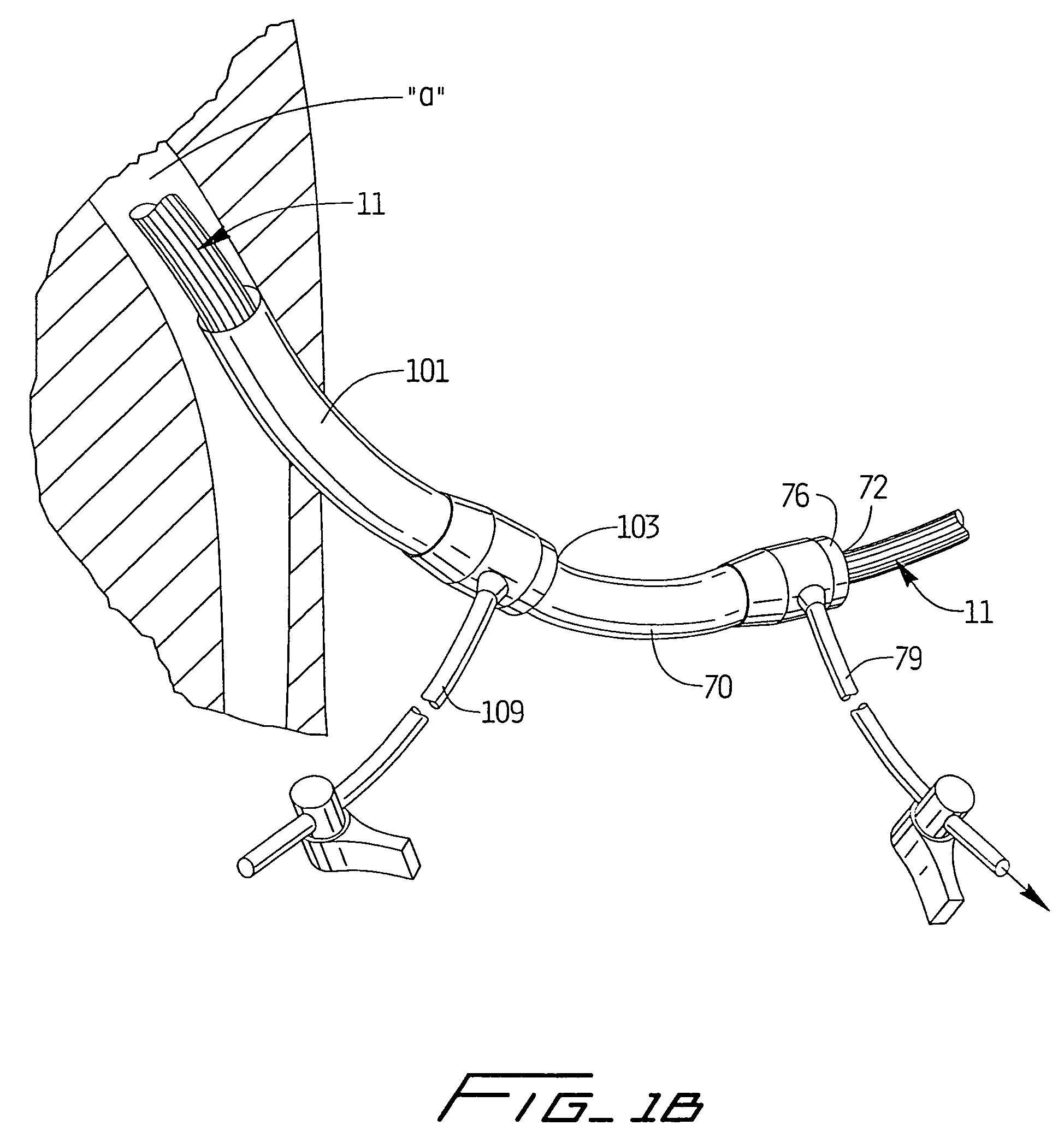
[0066] Turning first to FIGS. 2A and 2B, a valve resecting instrument is designated by reference numeral 50. Resecting instrument 50 is inserted through delivery catheter 70. Delivery catheter 70 is inserted through a small incision in the patient's leg to access the femoral artery (not shown), retained within sheath 101 (see FIG. 1), and advanced through the femoral artery and around the aortic arch “b” to access the patient's defective valve. Delivery catheter 70 has slit valves 72, 74 on its proximal and distal ends 76,78, respectively, to maintain a fluid seal when surgical instruments are inserted into the lumen 77 of the delivery catheter 70. Thus, blood and debris are prevented from entering into the lumen 77 except for removal of resected valve tissue as described below. Delivery catheter 70 has a side tube or arm 79 connected to a suction source to remove the resected valve tissue.

[0067] Resecting instrument 50 has a flexible outer tube 58, a pair of resecting jaws 56 exten...

second embodiment

[0083]FIG. 14 illustrates the valve leaflets 50 in the closed position, where they converge at their tips during diastole. Their systolic or open position is illustrated in FIG. 13. It should be appreciated that the rounded edge, curved leaflets of the embodiment of FIG. 8 could alternatively be used with the valve of FIG. 12-14.

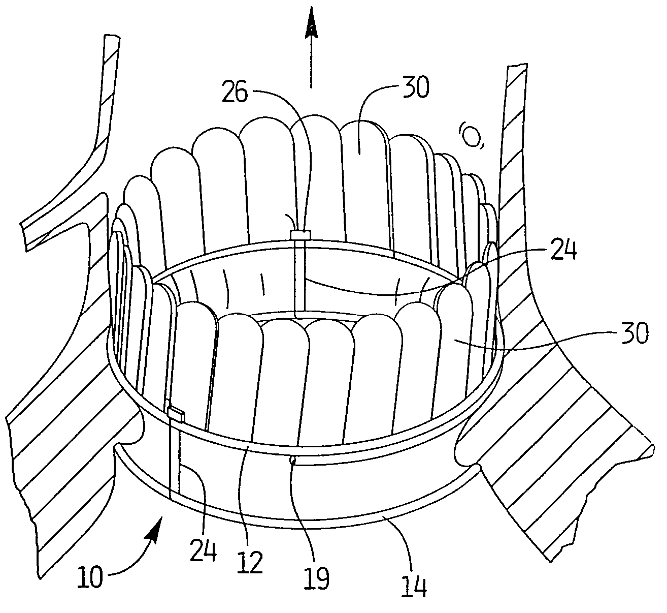
[0084] Various alternate embodiments of valve leaflets are disclosed in FIG. 15-30 and will now be described. The leaflets need to accommodate two competing requirements: long term stability to handle repeated opening and closing without inverting or undesirably contacting the vessel wall and flexibility for unimpeded opening and closing to simulate natural valve function. The embodiments described below are intended to strike a balance between these two requirements. It should be understood that these leaflet configurations could be used with either of the two valve embodiments 10, 40 described above. Additionally the leaflets can be attached to the surface...


PUM


Abstract

The present invention provides a valve configured for insertion on the proximal and distal sides of a heart valve annulus to replace the heart valve of a patient. The valve comprises a first substantially annular portion adapted to be positioned on a proximal side of the annulus of a patient and a second substantially annular portion adapted to be positioned on a distal side of the annulus of a patient, wherein at least one of the first and second substantially annular portions is movable towards the other portion to a clamped position to clamp around the annulus. The second portion has a flow restricting portion extending therefrom and is movable between a first position to permit the flow of blood and a second position to restrict the flow of blood. In one embodiment, the valve has a suture joining the first and second portions to draw the first and second portions into closer proximity and a cinch member to secure the suture to maintain the first and second portions in the clamped position. In another embodiment, the first and second portions are connected by a first segment which biases the first and second portions toward the clamped position.

Description

[0001] This application claims priority from PCT application no. PCT / US / 01 / 43879, filed Nov. 14, 2001 which claims priority from Provisional application No. 60 / 252,187, filed Nov. 21, 2000.BACKGROUND [0002] 1. Technical Field [0003] This application relates to a prosthetic valve and more particularly to a prosthetic valve for minimally invasive replacement of a patient's cardiac valve. [0004] 2. Background of Related Art [0005] The aortic and mitral valves are heart valves that open and close automatically in response to the pumping of the heart to control blood flow. The aortic valve is open during ventricular systole, when the heart is in contraction and blood is surged through the aorta and pulmonary artery, and is closed during diastole, when the heart is in relaxation, dilates and the cavity fills with blood. The aortic valve is positioned between the left ventricle and ascending aorta and functions to prevent back flow into the ventricle. The mitral or bicuspid valve closes th...

Claims


Application Information

Patent Timeline
Patent Type & Authority Applications(United States)
IPC IPC(8): A61F2/24A61B17/00
CPCA61B2017/00243A61F2/2436A61F2/2421A61F2/2412A61F2230/0091Y10S623/904
Inventor MCGUCKIN, JAMES F. JR.HINCHLIFFE, PETER W.J.
Owner REX MEDICAL LP
Why Eureka
Try Eureka