Coupled inductor DC/DC converter

a converter and coupled inductor technology, applied in the direction of dc-dc conversion, power conversion systems, instruments, etc., can solve the problems of severe rectifier reverse recovery problems of ccm boost converters, huge turn-on current spikes of active switches of converters, and high switching turn-on loss, etc., to improve efficiency, cost-effective

Inactive Publication Date: 2006-01-19
VIRGINIA TECH INTPROP INC
View PDF2 Cites 66 Cited by
  • Summary
  • Abstract
  • Description
  • Claims
  • Application Information

AI Technical Summary

Benefits of technology

[0013] The present invention to provides a simple solution to alleviate the rectifier reverse recovery problem. The proposed passive solution keeps the advantage of simplicity of the passive approaches, while the invented circuit does not suffer from voltage or current stress. By only adding one extra rectifier and one coupled winding to the boost inductor, the current through the original rectifier could be steered to a new branch. By careful design, the current through the original rectifier could be reduced to zero before t

Problems solved by technology

At high power levels, CCM boost converters have severe rectifier reverse recovery problems due to a high forward current and high output voltage.
As a result, the active switch of the converter has huge turn-on current spikes.
Such turn-on spikes are not only responsible for the high switching turn-on loss but also bring severe electromagnetic interference (EMI) noises.
Fast recovery rectifiers could reduce reverse recovery charge with various effects if the boost rectifiers are “hard” switched, which means that the rectifier current turn-off rates di/dt are not controlled.
Under “hard-switching” conditions, thermal management is difficult to deal with by using silicon rectifiers such as MUR860 and MURH860 at high power levels.
Although the GaAs rectifiers' performance is

Method used


Image

  • Coupled inductor DC/DC converter
  • Coupled inductor DC/DC converter
  • Coupled inductor DC/DC converter

Examples


Embodiment Construction

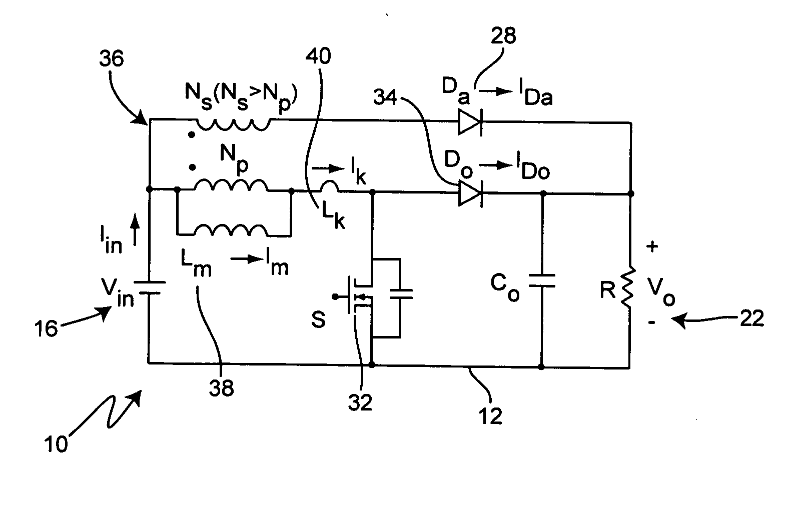
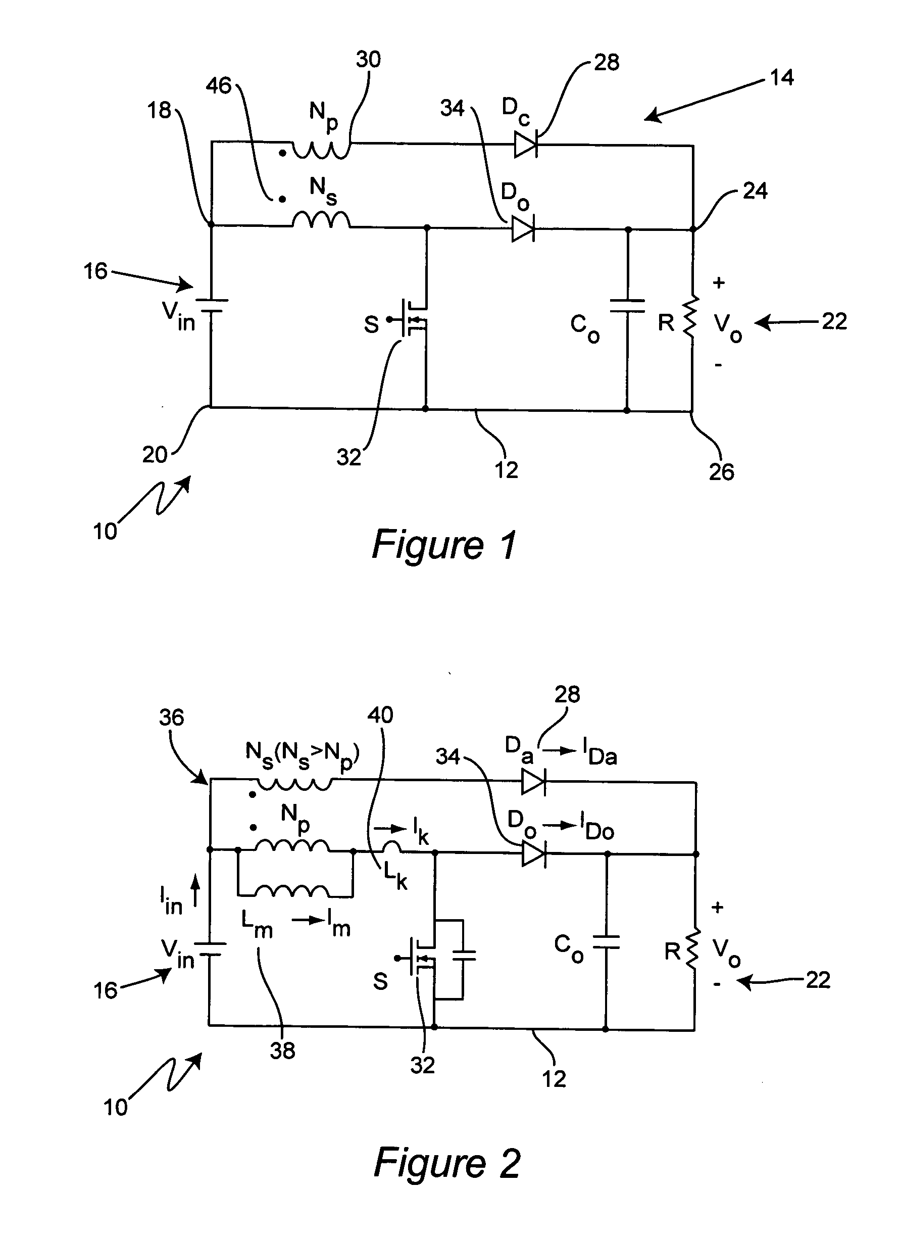
[0053] In a most basic embodiment, the present invention is a DC / DC converter for managing high voltage gain that includes an input side having a high tap and a low tap, an output side having a high tap and a low tap, a converter circuit interconnecting the input side and the output side, and a steering branch having at least one rectifier and one of at least one winding and a capacitor. The steering branch interconnects the input side with the output side. The converter circuit is preferably selected from the following types of conventional converter circuits: buck, boost, buck-boost, Cuk, Sepic, Zeta, half bridge boost for low-line input, half bridge boost for high-line input, and half bridge boost for universal-line input.

[0054] Referring now to the drawings, and more particularly to FIG. 1, there is shown a circuit diagram of a DC / DC converter, shown generally at 10, employing a boost converter circuit 12 with a steering branch, shown generally at 14, in accordance with the pre...


PUM


Abstract

DC/DC converter for managing high voltage gain that includes an input side having a high tap and a low tap, an output side having a high tap and a low tap, a converter circuit interconnecting the input side and the output side, and a steering branch having at least one rectifier and one of at least one winding and a capacitor. The steering branch interconnects the input side with the output side. The converter circuit is preferably selected from the following types of conventional converter circuits: buck, boost, buck-boost, Cuk, Sepic, Zeta, half bridge boost for low-line input, half bridge boost for high-line input, and half bridge boost for universal-line input. The DC/DC converter uses coupled inductor to shift the original rectifier current to an added branch and then control the rectifier current decrease rate in the new branch when rectifier turns off.

Description

CROSS-REFERENCE TO RELATED APPLICATIONS [0001] This application claims priority to U.S. Provisional Application Ser. No. 60 / 200,003, filed on Apr. 27, 2000, and Ser. No. 60 / 231,556, filed on Sep. 11, 2000.DESCRIPTION BACKGROUND OF THE INVENTION [0002] 1. Field of the Invention [0003] The present invention generally relates to DC to DC converters and, more particularly, to DC to DC coupled inductor converters. [0004] 2. Background Description [0005] Continuous current mode (CCM) boost converters are widely used as front-end converters for active input current shaping. The output voltage of these kinds of front end converters for power factor correction (PFC) is generally higher than 375V for universal line applications because the output voltage of a boost converter has to be larger than the input peak voltage. At high power levels, CCM boost converters have severe rectifier reverse recovery problems due to a high forward current and high output voltage. As a result, the active switc...

Claims


Application Information

Patent Timeline
IPC IPC(8): G05F1/24
CPCH02M3/155
Inventor ZHAO, QUNLEE, FRED C.XU, PENG
Owner VIRGINIA TECH INTPROP INC
Why Eureka
Try Eureka