Support system for use when performing medical imaging of a patient

a technology for supporting systems and patients, applied in the field of patient support racks, can solve the problems of increased personnel requirements, reduced ability to generally immobilize patients, and potential injuries to hospital personnel due to lifting

Inactive Publication Date: 2006-01-26
CIVCO MEDICAL INSTR CO
View PDF42 Cites 52 Cited by
  • Summary
  • Abstract
  • Description
  • Claims
  • Application Information

AI Technical Summary

Benefits of technology

[0043] Some platforms of the present invention may include both curved portions and flat portions. The curved portions, for example including a concave section, may be configured to retain a patient and may have a radius of greater than about 50 cm, greater than about 60 cm, or greater than about 70 cm. Flat portions may be provided proximate the edges of the platform and may form flanges configured to hold supplemental medical equipment. The flat portions may be parallel to one another and coplanar, allowing ease of positioning of medical equipment along the perimeter of the tray. In addition, the flat portions along the edges of the tray may be coplanar with a plane of travel of the tray within the scanning instrument. In some embodiments, the flat portions may be at least about 10 mm wide, at least about 20 mm wide, at least about 30 mm wide, or at least about 40 mm wide. The flat portions may extend away from the centerline of the tray on a plane spaced from the lowermost portion of the tray, thus allowing room to fasten through or around the edges of the tray by providing access to the underside thereof. The tray may be 10 mm or less in thickness at its curved portions, or may be less than 25 mm thick throughout. The tray instead may vary in thickness.
[0044] In some embodiments, the tray may contain coupling portions or holes configured to receive supplemental medical equipment. The holes may be threaded in some embodiments, or may have threaded inserts therein. The holes may allow rapid manual fixation of supplemental medical equipment and also may not interfere with image acquisition. In another embodiment, the edges of the tray may be configured as a rail, thus permitting a user an infinite choice of positions for instrument fixation as compared to a fixed number of defined points provided by threaded holes. Such a rail may be provided with teeth and function as a gear rack for permitting encoded motion of an arm or guidance device along its length.

Problems solved by technology

Such extensive repositioning of the patient has numerous disadvantages, including a reduced ability to generally immobilize the patient, increased personnel requirements due to assisting or lifting the patient from one support to another, and even the potential for injuries to hospital personnel because of the lifting.
Nevertheless, a standard patient support suitable for use in multiple hospital environments thus far has not been introduced because of the diverse design requirements that must be met for widespread application.
In contrast, in the imaging setting, many materials may not be present with the patient due to interference with the operation of the imaging equipment.
CT is known to be particularly useful for volumetric imaging but also suffers from poor soft tissue contrast, while MRI offers multi-planar imaging with superior soft tissue contrast.
The use of CT and MR for intraoperative imaging and interventional radiology (e.g., performing minimally invasive, targeted treatments using imaging for guidance) previously has been limited because of the substantial challenges posed by the geometry and overall size of the imaging equipment.
The donut-shaped, ring-type gantries of traditional CT and MR equipment, for example, are not easily accommodated in operating rooms, and can cause or suffer from various deleterious effects due to interactions with other equipment.
Until recently, only simple procedures such as biopsy or aspiration of fluid were performed in these scanners, and the need for additional capabilities in the support or table was limited.
Also, some newly developed surgeries simply cannot be done without concurrent CT or MR image guidance.
The surrounding geometry of the imaging equipment, along with the requisite patient translation during scanning, presents a challenge when performing invasive procedures that require or are benefited by having equipment that ideally should remain in a fixed relationship to the immobilized patient.
However, as procedures are becoming more complex and, in particular, as CT and MR imaging equipment are moved into the operating room environment, there is a need for new approaches.
Some materials suitable for use in patient supports and associated components for use in the operating environment are unsuitable for use in the imaging environment.
Such metal objects may cause poor image resolution and result in image artifacts that can mask or be misinterpreted as pathology.
Concomitantly, metal objects present a safety hazard to the patient due to their attraction to the magnetic source (e.g., becoming projectiles due to their attraction by the magnet to the vicinity of the scanner table).
Carbon fiber, a radiolucent material that is essentially transparent to x-rays, often is used in the CT setting but not generally accepted for use with an MRI scanner.
One resulting problem is that this anatomical motion can adversely affect data acquisition, causing so-called ghost, or motion artifacts and thus adversely affect image quality.
A second problem arises when interventional procedures are done because of the inability of a patient to precisely repeat a given breath.
A comparable, clinically practical, real time signal of respiratory phase or internal organ position that can be used with CT or MR has not been available to date.
It is especially problematic in the patient who is breathing voluntarily and not intubated with an endotracheal tube where volume input may be controlled.
While standard operating tables, for example, may be fitted with a broad range of accessories and attachments to facilitate a wide array of operations, the versatility and convenience provided by such a standard operating table is currently unavailable for use during CT or MR imaging using the supports currently employed therewith.

Method used


Image

  • Support system for use when performing medical imaging of a patient
  • Support system for use when performing medical imaging of a patient
  • Support system for use when performing medical imaging of a patient

Examples


Embodiment Construction

[0073] Terms such as “cephalad,”“caudal,”“upper” and “lower” as used herein are provided as non-limiting examples of the orientation of features.

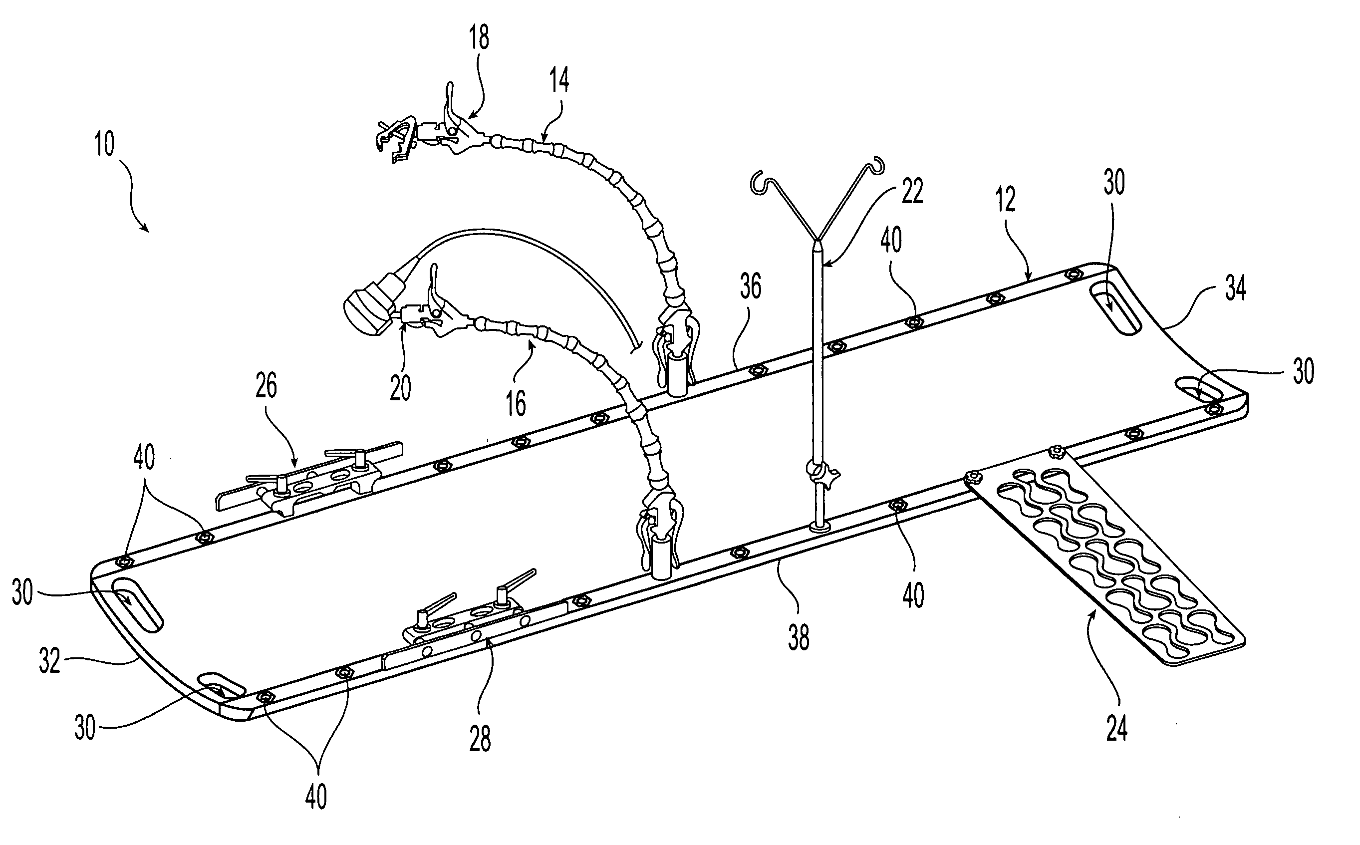
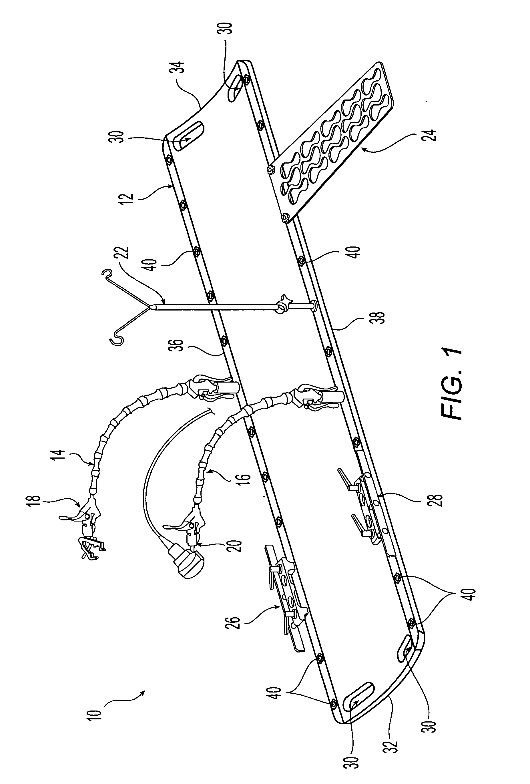
[0074] Referring initially to FIG. 1, a support system 10 according to the present invention is shown with a variety of components coupled thereto. Support system 10 includes a tray 12, curvilinear articulating arm assemblies 14, 16, end effectors 18, 20 coupled to arms 14, 16, IV pole 22, arm board 24, and rail assemblies 26, 28. A variety of end effectors may be demountably attached to the ends of arms 14, 16 to assist a technician or practitioner with a medical / imaging procedure or provide other features useful with respect to a patient. End effector 18, for example, is configured as a bracket or clamp, while end effector 20 is configured as a self-centering abdominal probe bracket.

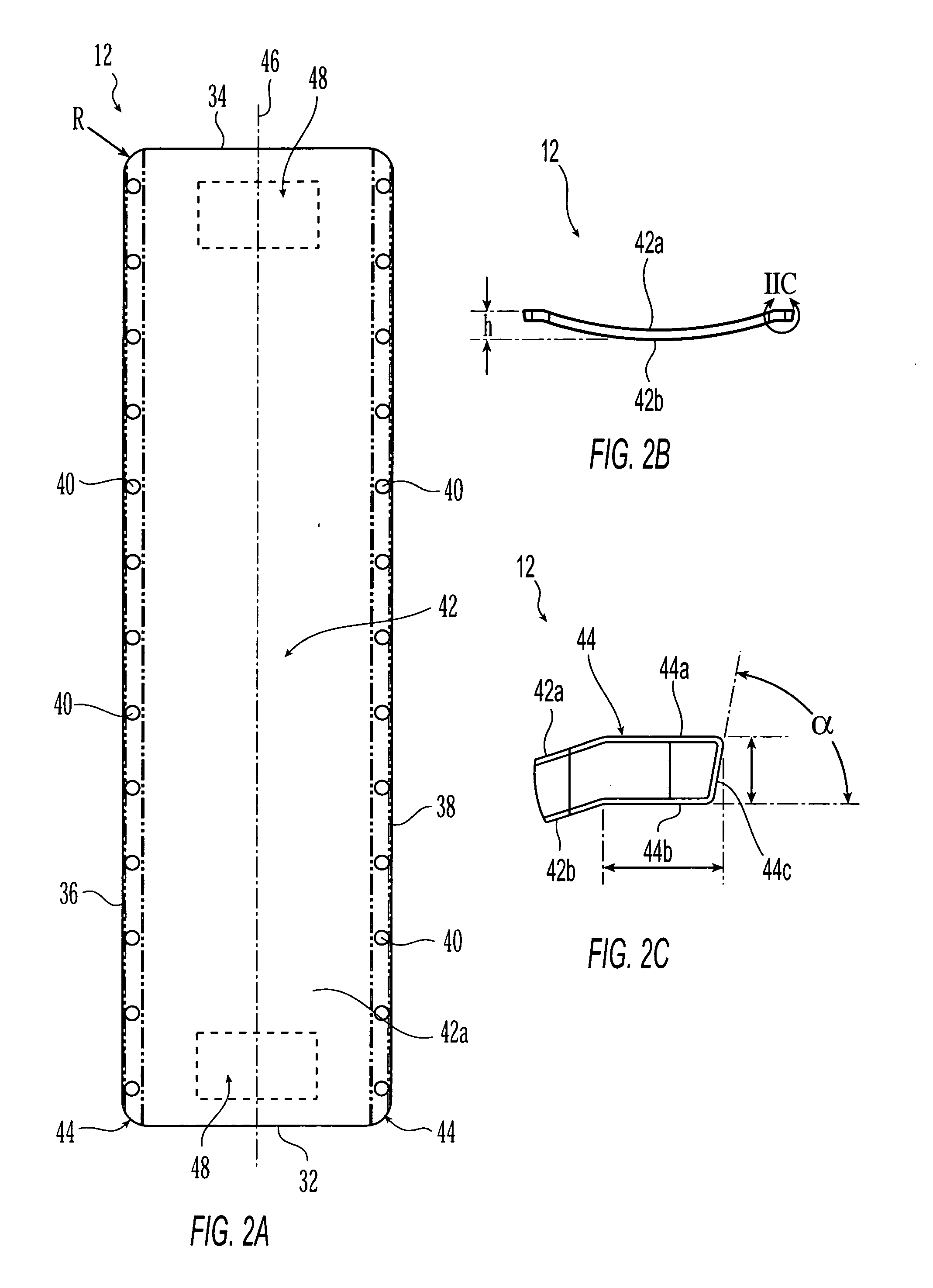
[0075] In a preferred exemplary embodiment, tray 12 includes two pairs of hold regions 30, each pair being disposed proximate a free cranial end 32 or free ...


PUM


Abstract

A system is provided for supporting a patient during computed axial tomography imaging. The system includes a movable platform formed of a radiolucent material, a discrete attachment region in the platform, and a curvilinear articulating arm coupled to the platform at the discrete attachment region. A method for supporting a patient during a plurality of procedures also is provided. The method includes: disposing the patient on a movable platform formed of a radiolucent material; positioning a device with respect to the patient, the device being disposed on a curvilinear articulating arm coupled to the platform; placing the platform, positioned device, and patient in a computed axial tomography imaging system and performing an imaging procedure.

Description

CROSS-REFERENCE TO RELATED APPLICATIONS [0001] The benefits of Provisional Application No. 60 / 559,414 filed Apr. 2, 2004, Provisional Application No. 60 / 575,792 filed May 28, 2004, and Provisional Application No. 60 / 614,593 filed Oct. 1, 2004 are claimed under 35 U.S.C. § 119(e), and the entire contents of these applications are expressly incorporated herein by reference thereto.FIELD OF THE INVENTION [0002] The invention relates to a support system for use when performing medical imaging of a patient. In particular, the invention relates to a patient support tray adapted to use in a variety of medical environments. BACKGROUND OF THE INVENTION [0003] Work-flows of patients from arrival at medical care facilities through post-operative recovery typically require a patient to be transferred among multiple supports on which the patient is transported and / or stabilized. For example, upon arrival at a hospital via an ambulance, a patient initially may be moved on a stretcher into the hos...

Claims


Application Information

Patent Timeline
Patent Type & Authority Applications(United States)
IPC IPC(8): A47B13/00A61B5/055A61B6/04A61B19/00A61G1/01
CPCA61B5/0555A61B6/0442A61B19/201A61B19/26A61B2019/268A61B6/4423A61G13/101A61G13/1275A61G2210/50A61B6/4417A61G1/01A61B5/055A61B90/11A61B90/50A61B2090/571
Inventor WHITMORE, WILLET F. IIIWILSON, ROGER F.ONIK, GARY M.BARZELL, WINSTON E.BRAUNER, STEPHEN E.
Owner CIVCO MEDICAL INSTR CO
Why Eureka
Try Eureka