Surface enhanced Raman spectroscopic nano-imaging probe and uses therefor

a raman spectroscopic and nano-imaging technology, applied in the field oframan spectroscopy and imaging, can solve the problems of limiting the use of sers as imaging techniques, limiting the spatial resolution of such analyses, and preventing the imaging of nanometer-scale objects, so as to prevent image warping

Inactive Publication Date: 2006-01-26
UNIV OF MARLAND BALTIMORE COUNTY THE
View PDF2 Cites 38 Cited by
  • Summary
  • Abstract
  • Description
  • Claims
  • Application Information

AI Technical Summary

Benefits of technology

[0017]FIGS. 1A-1D depict the SERS nano-imaging probe and a surface enhanced Raman spectroscopic nanoimaging system. FIG. 1A is a schematic of a cross-sectional view of the SERS nano-imaging probe showing the component parts. FIGS. 1B-1C show microscope images of a tapered fiber optic probe as shown perpendicular (FIG. 1B) to the microscope stage and parallel viewing the non-tapered end (FIG. 1C). The tapered flat surface prevents warping of images through the fiber bundle. FIG. 1D is a schematic of the SERS nanoimaging system.

Problems solved by technology

However, the creation of uniform roughened metal surfaces, necessary for SERS, and thus uniform surface enhancement, is difficult to control from location-to-location which dramatically limits the use of SERS as an imaging technique (22-25).
Additionally, the far-field imaging methodologies employed in conventional chemical imaging analyses ultimately limits the spatial resolution of such analyses to the diffraction limit of light, effectively preventing the imaging of nanometer scale objects.
While NSOM in conjunction with other spectroscopic techniques can be used to produce high-resolution chemical images below the diffraction limit of light, dynamic real-time sample imaging has not yet been feasible, as NSOM requires hours of scanning the probe tip across the surface (36).
In addition, if a particular area of interest is found, it is often difficult to return to this exact location after the scan has been completed (36).
Due to these limitations, NSOM is not particularly suited to studying dynamic chemical events.
More specifically, the prior art is deficient in a SERS nanoimaging probe having a uniform, repeatable and regular nano-structured surface effective for nanoscale resolution and methods of making the same.

Method used


Image

  • Surface enhanced Raman spectroscopic nano-imaging probe and uses therefor
  • Surface enhanced Raman spectroscopic nano-imaging probe and uses therefor
  • Surface enhanced Raman spectroscopic nano-imaging probe and uses therefor

Examples


example 1

Fabrication of Tapered Fiber Optic Imaging Bundle

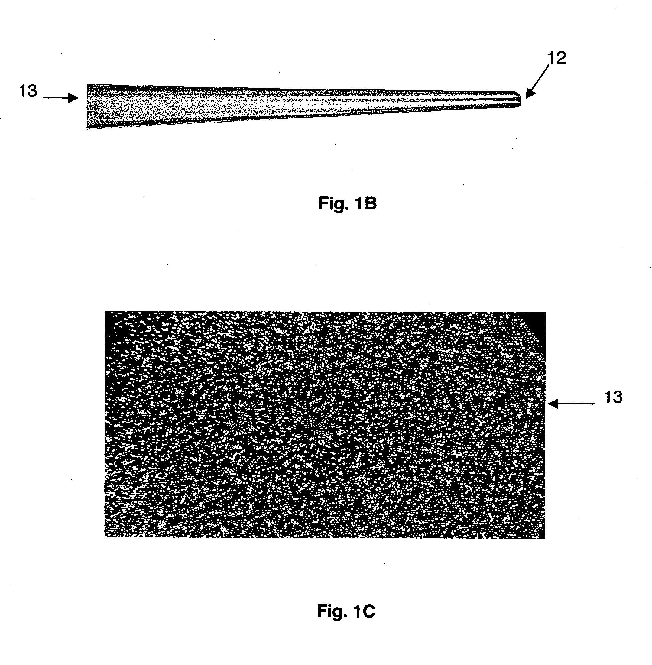
[0046] Both ends of a 3-inch section of fiber optic imaging bundle are polished smooth using lapping paper. A one-inch section of protective jacket is removed from the center of the fiber bundle through mechanical processes, e.g., removal with a razor blade. The polished and jacket-stripped fiber is then suspended between the two tension mount clamps of a CO2 laser based micropipette puller (Sutter Instruments P-2000) and tapered. The micropipette puller utilizes a CO2 laser to heat the fiber while a tension device pulls along the fiber axis. By varying the programmable pulling parameters, i.e., temperature, heat time, cooling delay time, and the force with which the tension mount clamps separate, flat, tapered probe tips of varying diameters are reproducibly created. As confirmed from SEM images of tapered bundles, an even heating throughout the entire bundle occurs, resulting in each fiber element being equally drawn. After being ...

example 2

Etching the Tapered Ends

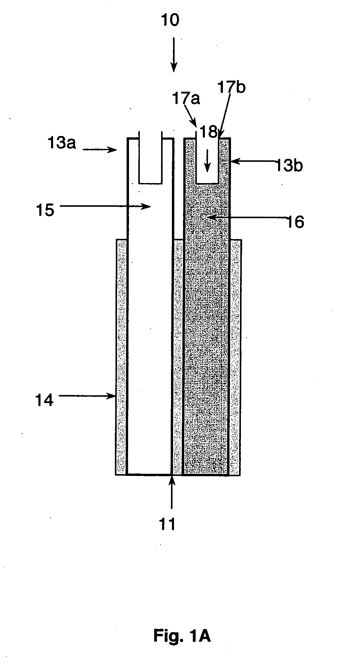
[0048] SERS active surfaces are applied to the tapered tip of the fiber optic imaging bundle to provide the chemical differentiation and imaging capabilities to the fiber optic nano-imaging probes while overcoming the SERS enhancement reproducibility issues associated with SERS imaging. The cladding surrounding each of the individual fiber elements provides the uniformly patterned underlying surface roughness upon which metal vapor is deposited via vacuum evaporation. The tapered fiber tips are placed in a solution of hydrofluoric acid in a process similar to that used to create microwell arrays in untapered fiber optic bundles (37-40). Due to the small size of the tapered fibers and the minimal amount of material to be etched out of the cores of the individual fiber elements, the tapered tips of the fibers were only suspended in the 25% hydrofluoric acid (HF; Aldrich) in water solution for periods of time ranging from 2-7 minutes depending upon the size of...

example 3

Silver Deposition

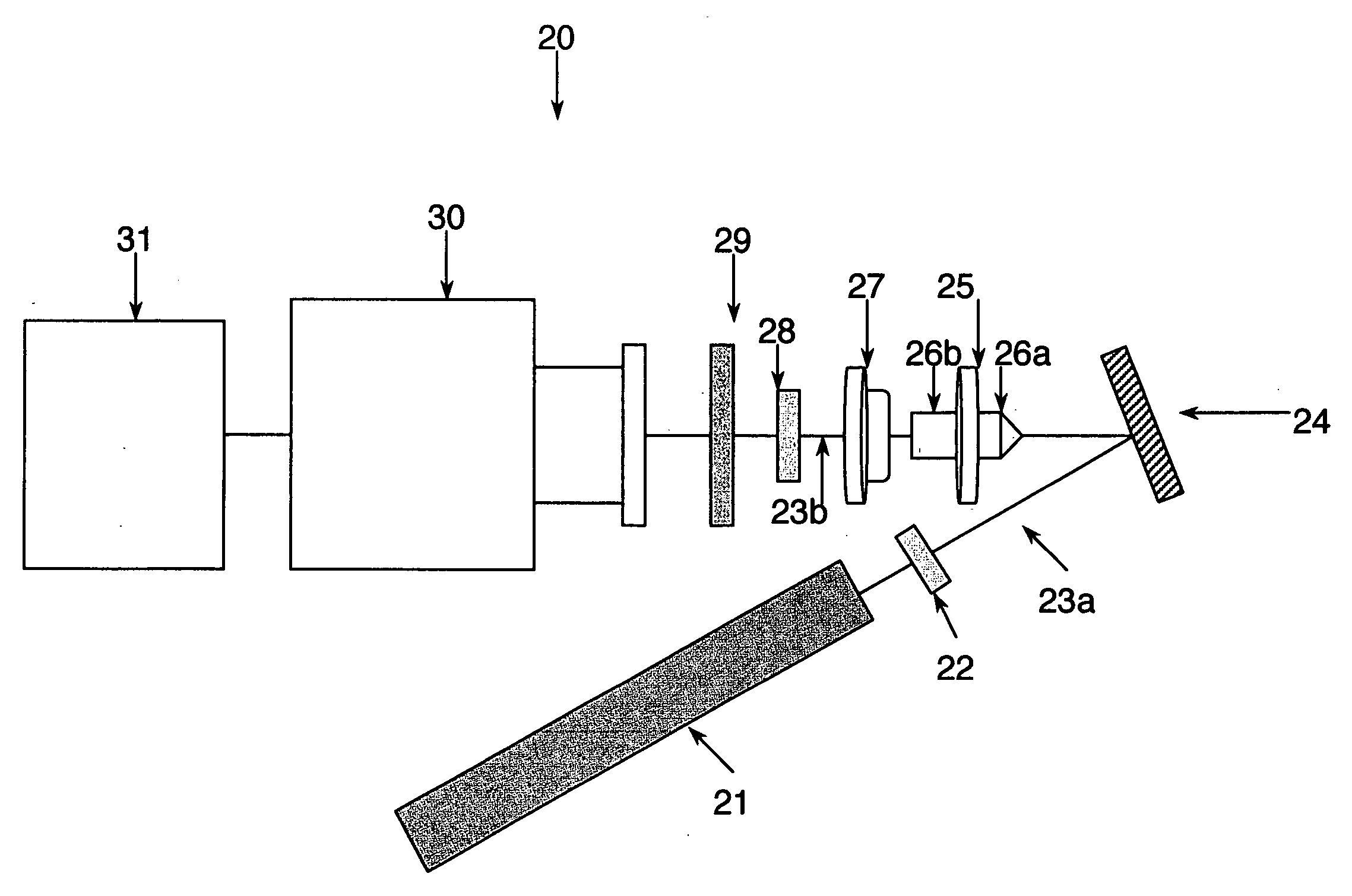
[0050] Once the desired underlying probe roughness was achieved with HF etching, an overlayer of silver is deposited by evaporating 99.999% pure silver shot (Kurt. J. Lesker Company) using an Explorer™-14 (Denton Vacuum) vacuum evaporator. In this procedure, the etched probe is suspended 15 cm above a tungsten boat (R. D. Mathis Company) containing the evaporating silver. The probes are oriented with the etched tips facing down toward the silver below and at a slight angle. This angle ensures that the silver selectively deposits on the cladding spikes instead of the cores, thereby providing a highly ordered silver island-like SERS structure. The silver is deposited at a rate of 1.8 nm / s, under a pressure of 3.0×10⁻⁶ Torr.

[0051] Monitoring of the amount of silver deposited is accomplished using a quartz crystal microbalance (Inficon XTM / 2 film thickness monitor) mounted beside the sample holder in the vacuum chamber. By depositing silver in this method, and varyin...


PUM

PropertyMeasurementUnit
diameteraaaaaaaaaa
diameteraaaaaaaaaa
diameteraaaaaaaaaa

Abstract

Provided herein is a reusable nano-imaging probe useful in surface enhanced Raman spectroscopic (SERS) applications demonstrating nanometer scale resolution. The nano-imaging probe generally comprises a fiber optic imaging bundle of fiber optic elements each having a tapered etched end and a non-tapered non-etched end. The tapered etched ends further comprise a SERS-active metal substrate deposited thereon effective to create a uniform SERS enhancement for an analyte or other substance of interest. Also provided is a SERS nanoimager for dynamic chemical imaging using the nano-imaging probe and methods of imaging and Raman spectral analysis and identification using the nano-imaging probe.

Description

CROSS-REFERENCE TO RELATED APPLICATION [0001] This non-provisional application claims benefit of priority to provisional U.S. Ser. No. 60 / 590,277, filed Jul. 22, 2004, now abandoned.BACKGROUND OF THE INVENTION [0002] 1. Field of the Invention [0003] This invention relates generally to the fields of Raman spectroscopy and imaging. Specifically, the present invention relates to a nano-imaging probe useful in surface enhanced Raman spectroscopic applications. [0004] 2. Description of the Related Art [0005] Recent technological advances in the controlled fabrication and manipulation of nanoscale systems and devices has generated increased interest in various nano-structures, both man-made, e.g., carbon nanotubes, (1-2) and naturally occurring, that is, biological cells or subcellular compartments (3). Synthesizing, characterizing and understanding such structures and their function, therefore, is extremely important to many fields ranging from drug delivery in the design of effective ti...

Claims


Application Information

Patent Timeline
Patent Type & Authority Applications(United States)
IPC IPC(8): G01J3/44G01N21/65
CPCG01N21/658
Inventor CULLUM, BRIAN M.HANKUS, MIKELLA EVONCHANDRASEKHARAN, NIRMALA
Owner UNIV OF MARLAND BALTIMORE COUNTY THE
Why Eureka
Try Eureka