

Rare-earth magnet
a technology magnets, applied in the field of rare earth magnets, can solve the problems of difficult use in a magnetic circuit requiring high magnetic flux, and achieve the effects of reducing noise in the magnetic circuit, improving overeall efficiency, and reducing loss
- Summary
- Abstract
- Description
- Claims
- Application Information
AI Technical Summary
Benefits of technology
Problems solved by technology
Method used
Image

Examples
example 1
[0014] An NdFeB alloy powder comprises Nd2Fe14B as a host phase in which an Nd rich phase is grown at a grain boundary of the main phase, with a grain size of 1 to 10 μm. NdF3 is thermal-sprayed onto the surface of such a ferromagnetic powder by plasma spraying etc. The NdF3 powder to be thermal sprayed has a powder diameter of 10 to 100 nm, and an NdF3 layer is formed on the surface of the ferromagnetic powder while moving the surface to be sprayed. Ar is used as a thermal spraying gas. NdF3 powder is thermal-sprayed onto the surface of the ferromagnetic powder while getting exposed to plasma. Those powders are heated in an inert atmosphere up to 200° C. to 300° C., pressed while getting orientated in magnetic fields, heated further and baked at 600 to 900° C. After baking, plural cross sections of the baked powders were evaluated with a transmission electron microscope or scanning electron microscope. As a consequence, it is confirmed that a rare-earth element-rich layer or an oxy...
example 2
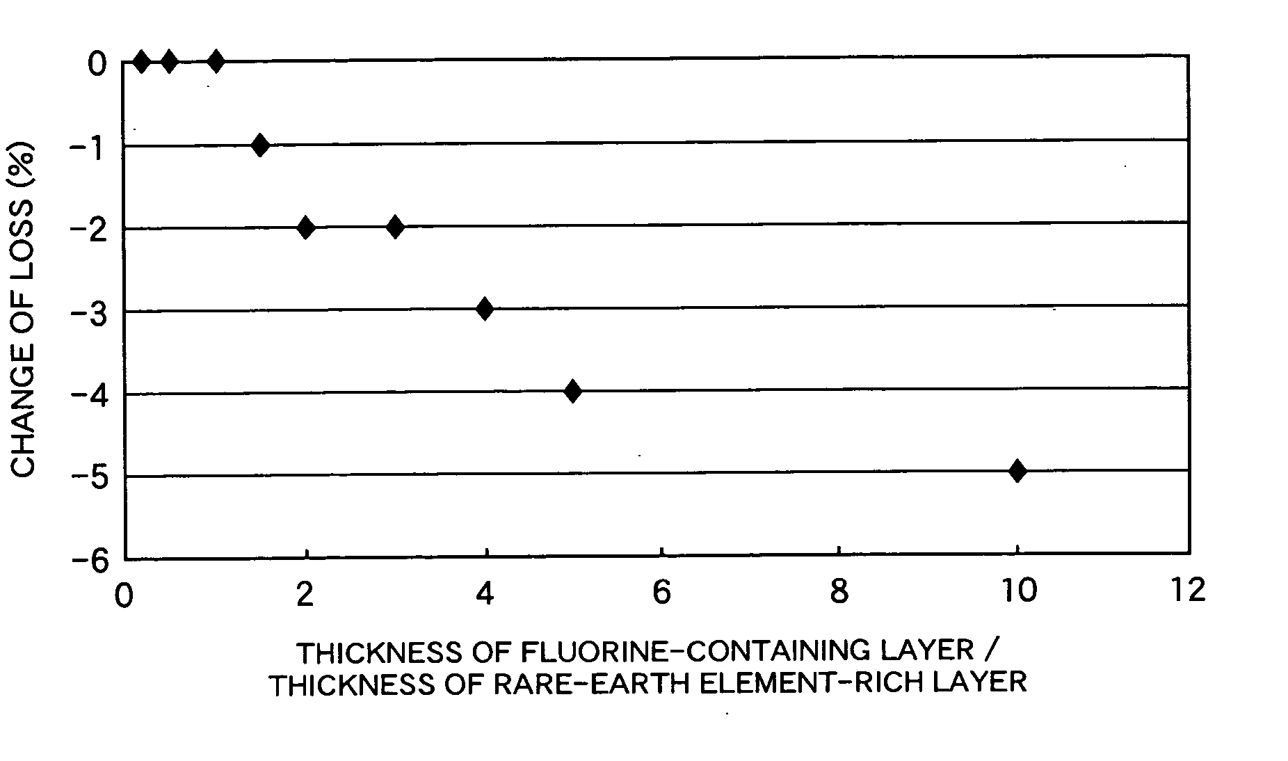
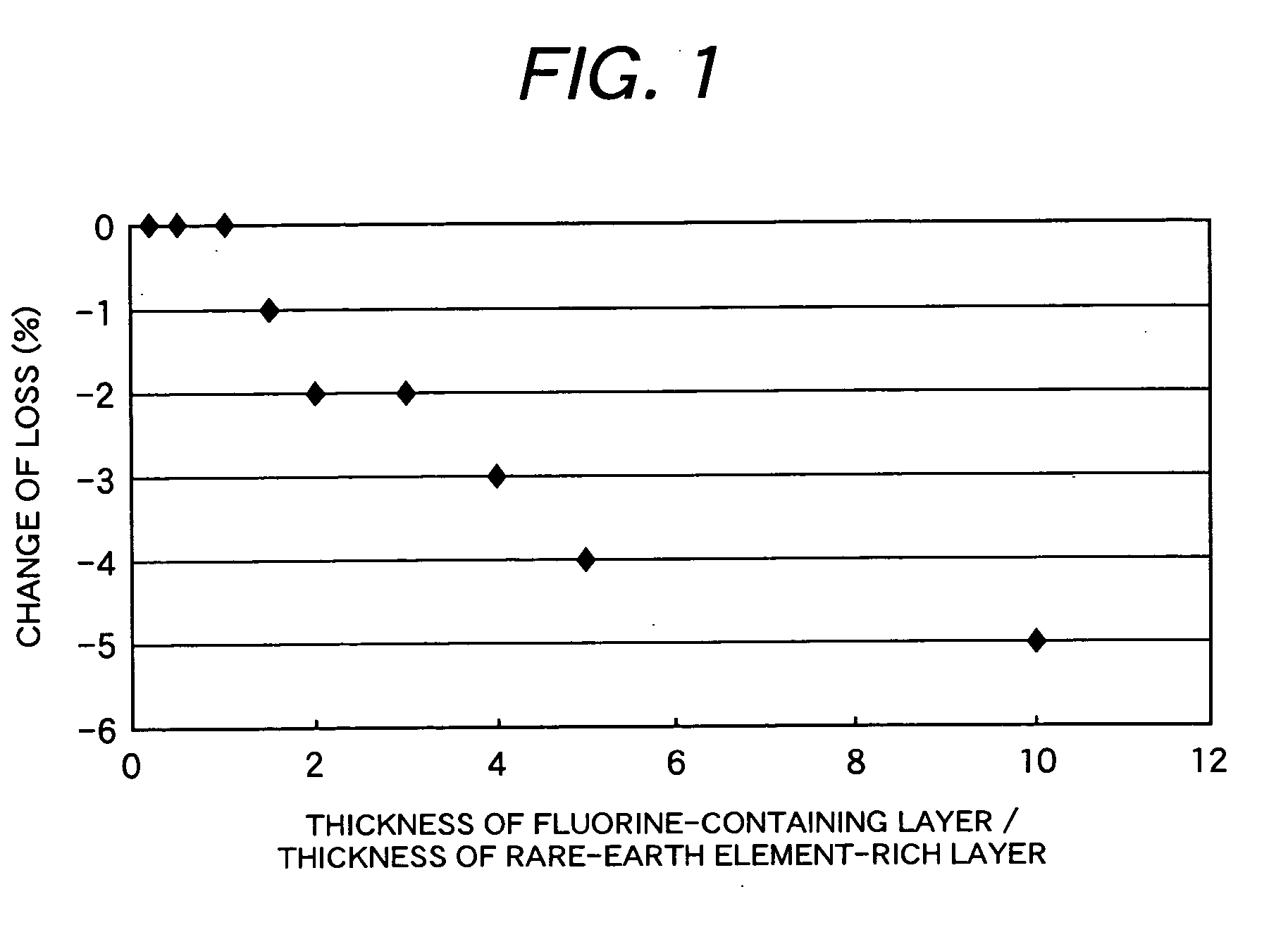
[0015] An NdFeB alloy powder is a powder which is pulverized into an average grain size of 1 to 10 μm, and NdF3 is sputtered onto the surface of the NdFeB powder. A fluorine-containing layer is formed on the surface of the NdFeB alloy powder by using a target molded from an NdF3 powder in an argon gas or a gas mixture atmosphere of argon and fluorine. If sputtering inversely on the powder surface before sputtering of the fluoride, the oxide layer is removed and on the powder surface can be cleaned. The NdFeB alloy powder undergoes vibration or rotational movement to form a layer containing a fluoride or fluorine over the entire NdFeB powder surface. A phase of 1 to 10 nm with a rare-earth element composition different from that of the host phase is present on the surface of the NdFeB alloy powder, and an oxide layer is often present in the vicinity thereof. The thickness of the phase with the rare-earth element composition different from the host phase and the thickness of the oxide...
example 3
[0016] For ferromagnetic powder containing at least one kind of rare-earth element such as an NdFeB powder, a fluorine-containing layer is formed on the surface of the ferromagnetic powder by using a solution containing at least one kind of alkaline earth element or rare-earth element, and fluorine. The fluorine-containing layer is grown entirely or partially on the surface of the ferromagnetic powder in the solution, and the grown fluorine-containing layer is formed along the powder surface. After removing the solvent from the powder surface, the ferromagnetic magnetic powder is heated at 600 to 1100° C., to increase a coercive force. After confirming that it exhibits a predetermined coercive force, it is oriented under magnetic fields, and molded by heating to obtain a molded product at a density of 90% or more. The molded product is magnetized to obtain a magnet. After increasing the coercive force, an organic material and a ferromagnetic powder formed with a fluorine-containing ...
PUM
| Property | Measurement | Unit |
|---|---|---|
| eutectic temperature | aaaaa | aaaaa |
| temperature | aaaaa | aaaaa |
| grain size | aaaaa | aaaaa |
Abstract
Description
Claims
Application Information