Wavefront sensing system employing active updating of reference positions and subaperture locations on wavefront sensor

a wavefront sensor and reference position technology, applied in the field of wave, can solve the problems of increasing reducing the density of the atmosphere, and generating the majority of wavefront errors, so as to improve the condition of the laser beam, automatically stabilizing the intensity of the received variation, and reducing the size of the spot

Active Publication Date: 2006-02-02
NORTHROP GRUMAN CORP
View PDF49 Cites 114 Cited by
  • Summary
  • Abstract
  • Description
  • Claims
  • Application Information

AI Technical Summary

Benefits of technology

[0059] Another object of the present invention is to provide a free-space adaptive optical laser communication system having optically-separated signal transmission and reception channels at all terminals in the communication system, wherein wavefront sensing (WFS) and wavefront correction (WFC) mechanisms are employed in the signal transmission and reception channels of system (i.e. traditional adaptive optics) to improve the condition of the laser beam at the signal detector in the signal reception channel (i.e. reduce the size of the spot at the detector plane).
[0060] Another object of the present invention is to provide a method of and apparatus for automatically stabilizing variations in the intensity of received laser beam carrier signals caused by atmospheric turbulence along the signal reception channels of a free-space adaptive optical laser communication system supporting optically-separated signal transmission and reception channels.
[0061] Another object of the present invention is to provide a free-space adaptive optical laser communication system supporting optically-combined signal transmission and reception channels and employing laser beam speckle tracking mechanism and speckle-to-fiber / detector locking mechanisms along the signal reception channels thereof for automatically stabilizing variations in the intensity of received laser beam carrier signals caused by atmospheric turbulence along said signal channels.
[0062] Another object of the present invention is to provide a free-space adaptive optical laser communication system having optically-combined signal transmission and reception channels at all terminals in the communication system, wherein wavefront sensing and wavefront correction mechanisms are employed in signal transmission and reception channels of all terminals in the communication system (i.e. adaptive optics) to improve the condition of the laser beam at the receiver (i.e. reduce the size of the spot a the detector plane).
[0063] Another object of the present invention is to provide a free-space adaptive optical laser communication system supporting optically-combined signal transmission and reception channels and employing speckle-to-receiver-aperture locking mechanism along the signal transmission channels of the system and laser beam speckle tracking mechanisms and speckle-to-fiber / detector locking mechanisms along the signal reception channels thereof for automatically stabilizing variations in the intensity of received laser beam carrier signals caused by atmospheric turbulence along said signal channels.
[0064] Another object of the present invention is to provide a free-space adaptive optical laser communication system having optically-combined signal transmission and reception channels at all terminals in the communication system; wherein wavefront sensing and wavefront correction mechanisms are signal transmission and reception channels of all terminals in the communication system (i.e. adaptive optics) to improve the condition of the laser beam at the receiver (i.e. reduce the size of the spot a the detector plane).

Problems solved by technology

In military applications, such laser communication systems and networks offer a level of superiority and security over radio-frequency (RF) based communication system which have relatively limited band-widths, and thus data transfer rates, as well as being susceptible to RF-based jamming techniques intended to interfere and disrupt the performance of such systems.
However, FSO laser communication systems are not without challenges and problems and challenges.
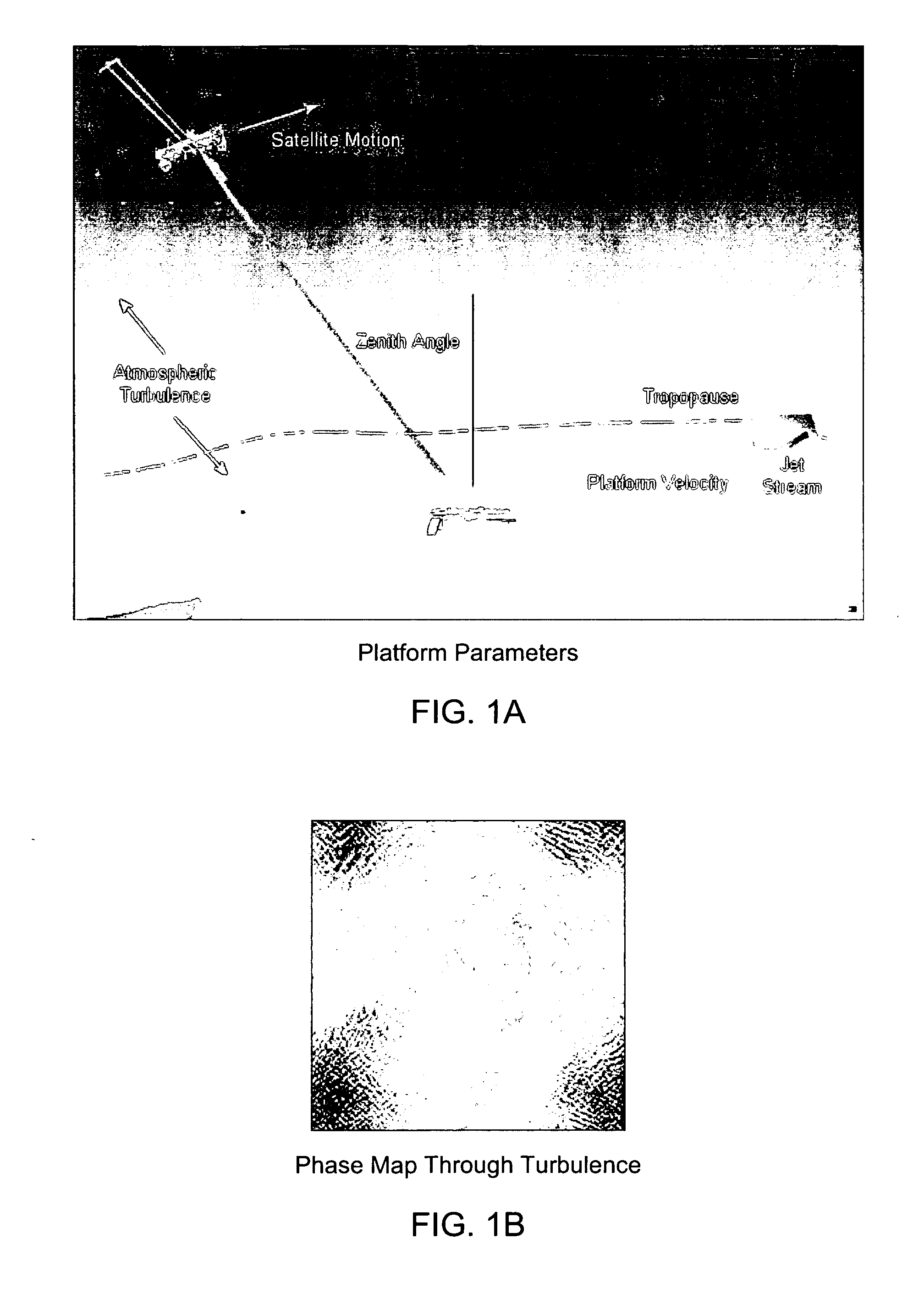
The density of the atmosphere declines rapidly with altitude and thus most of the wavefront errors are generated close to the aircraft.
For the light propagating up to the aircraft the wavefront errors picked up close to the aircraft evolve along the long path to the satellite so that the beam that reaches the satellite has both phase and intensity errors.
Therefore, the airborne to space borne direction as being the most problematic direction in this link.
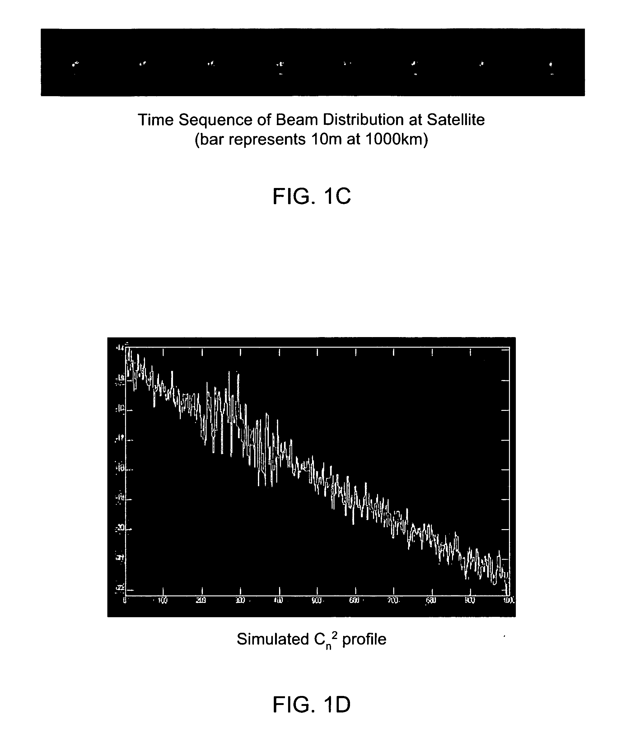
Such an event would lead to a deep fade of the link signal for any receiver aperture of less than a few meters diameter.
Difficulties arise when this point-ahead angle becomes larger than the isoplanatic angle of the atmospheric turbulence.
If the point-ahead angle is larger than the isoplanatic angle, the wavefront error measured from a source co-located with the satellite does not correctly represent the aberrations that will be experienced along the path of the transmitted beam.
Also, as wavefront tilt is the strongest atmospheric aberration, this aniosplanatic effect can lead to serious pointing errors in the transmitted laser beam if the employed laser beam tracking algorithm uses only the satellite apparent position to estimate the error.
However, the laser beam profile on the right shows that significant fade events can occur as the receiver aperture could easily lie within one of the dark (speckle) regions of the laser beam spot image.
Also, as turbulence is a random process, there will be occasions when higher order aberrations are strong enough to further disrupt the laser beam profile.
Unfortunately, under conditions like those of the Wave-Optic Propagation Simulations described above, the performance of phase only AO compensation systems is very limited.
Portions of the received beam with very low intensity lead to erroneous phase measurements and corrupt the calculated wavefront.
While techniques exist for doing this, none have been demonstrated in the field.
There are the same problems due to regions of low intensity in the receiver pupil mentioned with regard to the transmit side of an AO compensation system.
However, if the phase is correctly measured and compensated, then the laser beam spot at the detector should approach a diffraction limited size.
This compensation system cannot do anything to reduce the size of variations in the power coming into the receiver.
On top of these basic physical limitations of AO compensation systems for horizontal paths, there are also large and costly engineering problems due to the high temporal frequency characteristics of atmospheric turbulence.
Such response characteristics are beyond the performance of any existing AO systems.
For many applications of wavefront sensing, the generation of this reference wavefront and its introduction into the wavefront sensor present significant difficulties.
In this case, there is no simple way to introduce the proper reference wavefront that will produce the correct measurement.
While prior art laser communications systems provide good examples of this problem, the same problems are nevertheless present in all AO systems.
If the fiber is slightly out of the correct focal plane, or if it is translated so that the plane wave that focuses onto the fiber is at an angle to the plane wave used to calibrate the sensor, then the control system will drive the wavefront to be plane at the WFS, but not optimally couple into the fiber.
Further, if the beam splitter between the WFS and the collection optic introduces different aberrations on the transmitted and reflected beams, then the control loop again will do the wrong thing by flattening the wavefront at the WFS.
Various several techniques also have been developed for addressing such “beam-fiber coupling” problems, which arise when the receiver fiber is slightly out of the correct focal plane or if it is translated so that the control system drives the wavefront to be planar at the WFS, but not optimally coupled into the fiber.
However, both of these compensation techniques have the same shortcoming: the magnitude of the misalignment between the tracking sensor and the receiver is not fixed; it can vary with temperature, gravity loading, vibration, etc.
Over the course of time, the alignment will degrade and the performance of the receiver system will be compromised.
This requirement limits the maximum allowable wavefront gradient in each subaperture of the Hartmann sensor.
Furthermore, the gradient cannot be so large that the spot moves out of its subarray.
This often leads to a limitation in overall system performance.
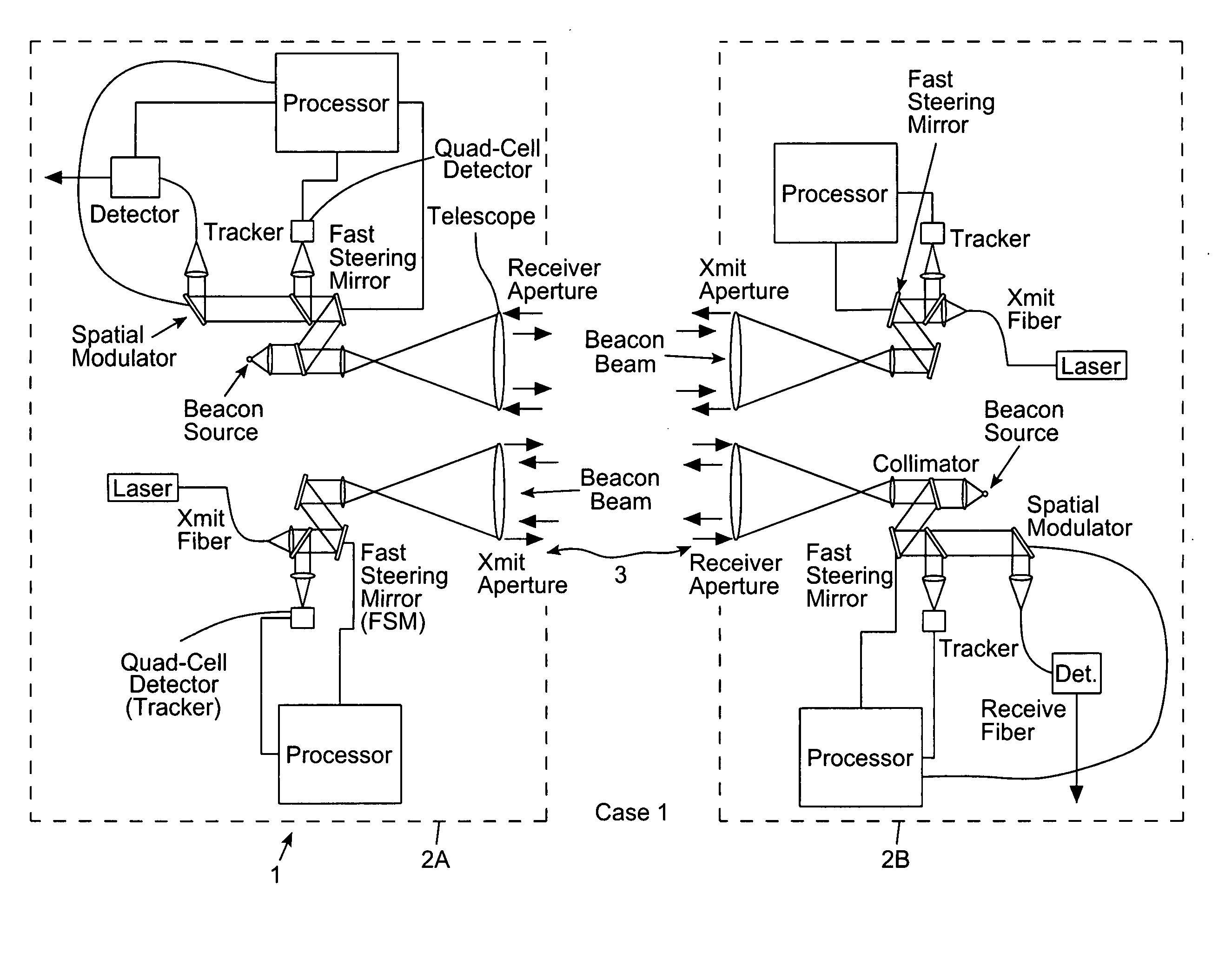
However, the transition of the light from fiber to free space presents problems.
Conversion of the light signals to electrical signals at very high rates places constraints on the physical size of the electro-optical sensor.
This means that the focal spot needs to be close to diffraction limited to properly couple the light from free space to the fiber.
Unfortunately, propagation of light through the atmosphere introduces aberrations in the optical wavefront that prevent reaching the diffraction limit.
However, under conditions of strong turbulence (such as encountered in a free space link close to the ground), the disturbance of the optical beam include both phase and intensity components.
Traditional phase only adaptive optics cannot compensate for these intensity disturbances.
The result is that FSO links under these conditions experience deep signal fade events that lead to unacceptable interruptions in the communications link.

Method used


Image

  • Wavefront sensing system employing active updating of reference positions and subaperture locations on wavefront sensor
  • Wavefront sensing system employing active updating of reference positions and subaperture locations on wavefront sensor
  • Wavefront sensing system employing active updating of reference positions and subaperture locations on wavefront sensor

Examples


Embodiment Construction

[0136] Referring to the figures in the accompanying Drawings, the various illustrative embodiments of the methods, systems and devices (i.e. instruments) of the present invention will be described in great detail, wherein like elements will be indicated using like reference numerals.

General Description of Laser Communications Link Fade Prevention Techniques of the Present Invention

[0137] Through research, Applicants have discovered that the spatial intensity variations in the received laser beam signal at the input plane of a receiver lead to temporal fluctuations in the total power received. FIG. 1K shows a simulation of a typical intensity distribution at the plane of the receiver aperture. This case is for a 10 km path through an atmosphere with Cn2=1.0×10⁻¹⁴ m−2.3. The transmitter and receiver apertures are both 20 cm in diameter and the wavelength is 1.5 microns. The full image shown is 1 m×1 m. This intensity pattern varies randomly as the turbulence along the path changes....


PUM


Abstract

A free-space adaptive optical laser communication system having signal transmission and reception channels at all terminals in the communication system, wherein wavefront sensing (WFS) and wavefront correction mechanisms are employed along signal transmission and reception channels of all terminals in the communication system (i.e. adaptive optics) to improve the condition of the laser beam at the receiver (i.e. reduce the size of the spot a the detector plane). in the illustrative embodiment, the WFS mechanisms employ a novel WFS control process, in which active updating of reference positions and subaperture locations on the wavefront sensor. These WFS mechanism can be used in diverse application environments, including but not limited to FSO laser communication systems.

Description

RELATED CASES [0001] The present application is a continuation-in-part (CIP) of co-pending U.S. application Ser. No. 11 / 057,863 filed Feb. 14, 2005, which is a CIP of U.S. application Ser. No. 10 / 777,476 filed Feb. 12, 2004; said patent application is assigned to and commonly owned by Metrologic Instruments, Inc. of Blackwood, N.J., and is incorporated herein by reference in its entirety.BACKGROUND OF THE INVENTION [0002] 1. Field of Invention [0003] The present invention relates to an improved bi-directional laser communications link between two optical transceiver platforms employing improved wavefront sensing (WFS) compensation mechanisms as a way of and a means for producing the highest possible resolution at the focal plane or maximizing the power into a communications fiber, and eliminating the physical misalignment between the communications fiber and the wavefront sensor, so as to improve communication link performance. [0004] 2. Brief Description of the State of the Art [00...

Claims


Application Information

Patent Timeline
Patent Type & Authority Applications(United States)
IPC IPC(8): H04B10/00
CPCH04B10/1125
Inventor WIRTH, ALLANJANKEVICS, ANDREW
Owner NORTHROP GRUMAN CORP
Why Eureka
Try Eureka