Catadioptric projection optical system, exposure apparatus having the same, device fabrication method

a projection optical system and catadioptric technology, applied in the field of projection optical systems, can solve the problems of chromatic aberration correction difficulties, increased apparatus cost, and large aperture of lens materials, and achieve the effect of superior stability and shortening distance (object-to-image distance)

Inactive Publication Date: 2006-02-09
CANON KK
View PDF5 Cites 42 Cited by
  • Summary
  • Abstract
  • Description
  • Claims
  • Application Information

AI Technical Summary

Benefits of technology

[0010] The present invention is directed to a catadioptric optical system that can shorten the distance (object-to-image distance) between the first o...

Problems solved by technology

However, the quartz and calcium fluoride are small differences in their dispersion values, and have difficulties in corrections to chromatic aberrations, especially, for the optical system that has very higher NA like the immersion optical system.
Moreover, lens materials larges an aperture along with higher NA, and increases an apparatus cost.
It is necessary to strong a refractive power of each lens to prevent the enlargement of the optical system according to a higher NA, and the aberration correction becomes difficult.
As a result, an incidence angle range and the maximum incidence angle to the plane mirror increase, and it becomes a serious problem for further higher NA by the immersion etc.
Therefore, it is undesirable to develop an exposure apparatus that has the optical system with a higher NA by the immersion etc. that neither the first object nor the second object are the position relationship of the parallel.
If such power arrangement is composed, the incidence angle range and the maximum incidence angle to the plane mirror arranged near the second intermediate image increase, and a light se...

Method used


Image

  • Catadioptric projection optical system, exposure apparatus having the same, device fabrication method
  • Catadioptric projection optical system, exposure apparatus having the same, device fabrication method
  • Catadioptric projection optical system, exposure apparatus having the same, device fabrication method

Examples


first embodiment

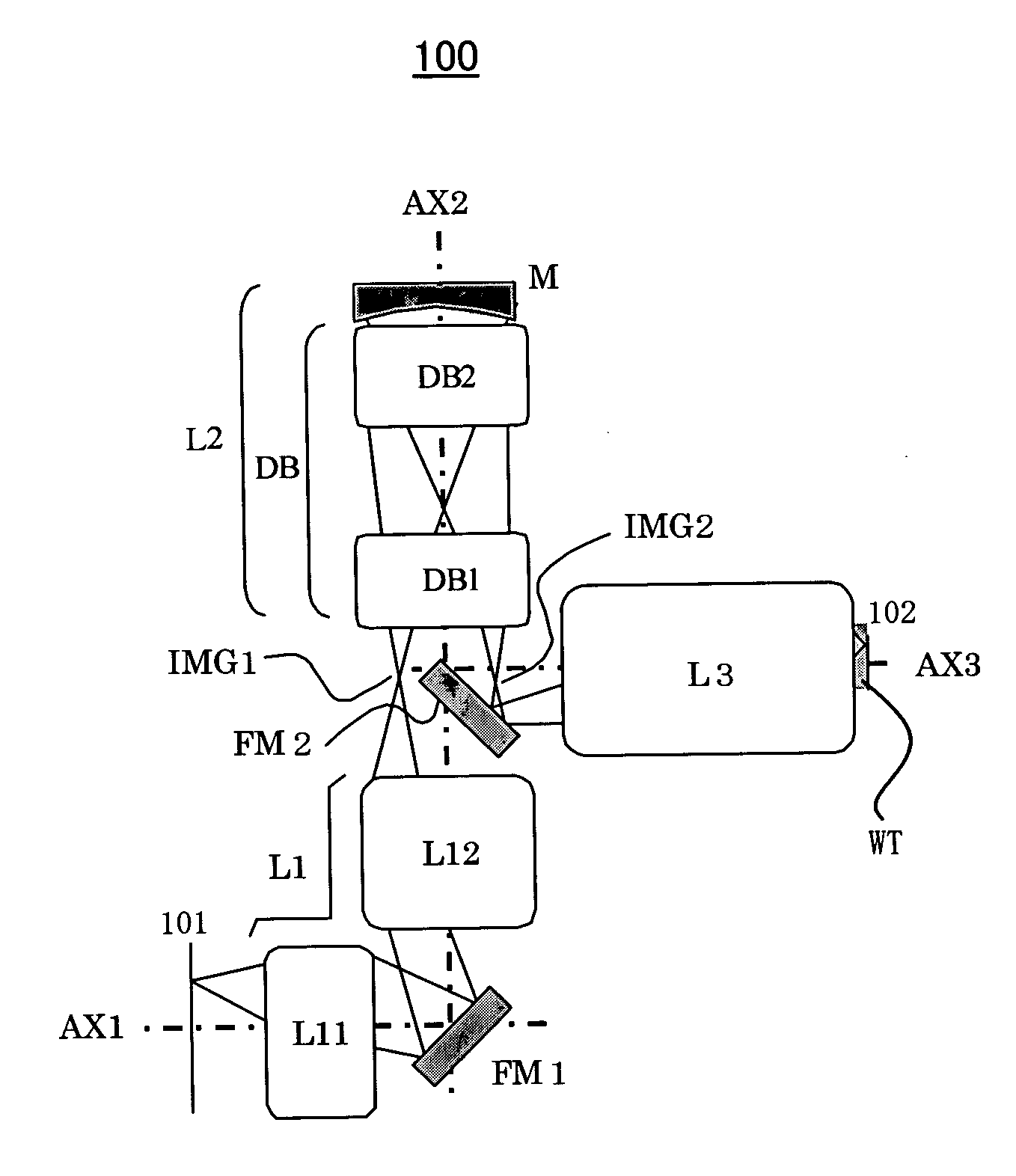
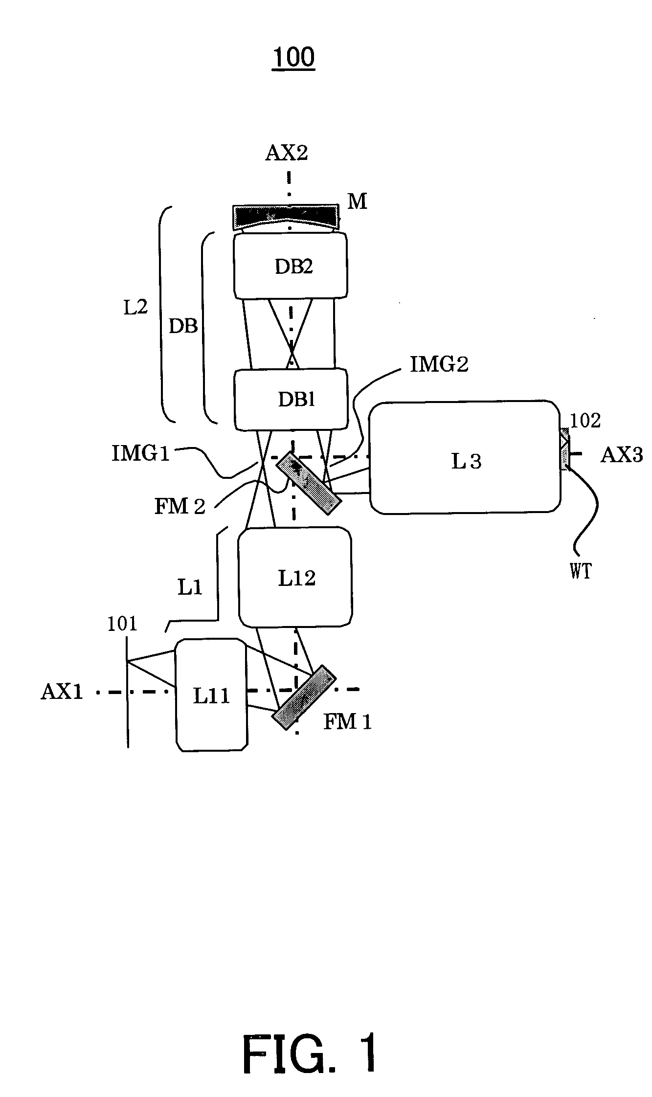
[0096]FIG. 9 is an optical-path diagram showing a specific lens formation of the catadioptric projection optical system 100 of the first embodiment. Referring to FIG. 9, the catadioptric projection optical system 100 includes, in order from the first object 101 side, a lens group (a first dioptric group) L1 that does not form a reciprocating optical system (double-pass optical system), a catadioptric group L2 that forms the reciprocating optical system (double-pass optical system), and a lens group (a second dioptric group) L3 that does not form the reciprocating optical system (double-pass optical system).

[0097] The lens group L1 includes a lens group (a first lens group) L11 having a positive refractive power and a lens group (a second lens group) L12 having a positive refractive power. The catadioptric group L2 includes a lens group (a third lens group) DB that forms the reciprocating optical system (double-pass optical system) and a concave mirror M. The lens group DB that form...

second embodiment

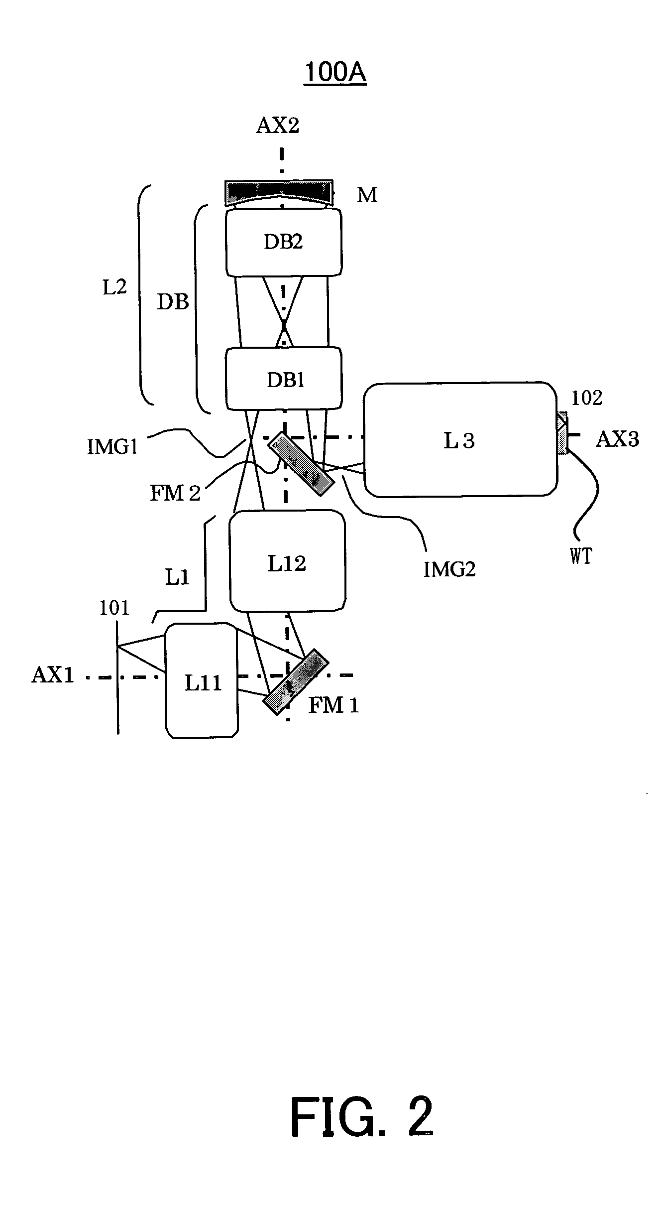
[0113]FIG. 11 is an optical-path diagram showing a specific lens formation of the catadioptric projection optical system 100 of the second embodiment. Referring to FIG. 11, the catadioptric projection optical system 100 includes, in order from the first object 101 side, a lens group (a first dioptric group) L1 that does not form a reciprocating optical system (double-pass optical system), a catadioptric group L2 that forms the reciprocating optical system (double-pass optical system), and a lens group (a second dioptric group) L3 that does not form the reciprocating optical system (double-pass optical system).

[0114] The lens group L1 includes a lens group (a first lens group) L11 having a positive refractive power and a lens group (a second lens group) L12 having a positive refractive power. The catadioptric group L2 includes a lens group (a third lens group) DB that forms the reciprocating optical system (double-pass optical system) and a concave mirror M. The lens group DB that f...

third embodiment

[0129]FIG. 13 is an optical-path diagram showing a specific lens formation of the catadioptric projection optical system 100 of the first embodiment. Referring to FIG. 13, the catadioptric projection optical system 100 includes, in order from the first object 101 side, a lens group (a first dioptric group) L1 that does not form a reciprocating optical system (double-pass optical system), a catadioptric group L2 that forms the reciprocating optical system (double-pass optical system), and a lens group (a second dioptric group) L3 that does not form the reciprocating optical system (double-pass optical system).

[0130] The lens group L1 includes a lens group (a first lens group) L11 having a positive refractive power and a lens group (a second lens group) L12 having a positive refractive power. The catadioptric group L2 includes a lens group (a third lens group) DB that forms the reciprocating optical system (double-pass optical system) and a concave mirror M. The lens group DB that fo...


PUM


Abstract

A catadioptric projection optical system for forming an intermediate image of a first object twice and for forming an image of the intermediate image onto a second object, said catadioptric projection optical system comprising, in order from the first object side and along an optical axis of said catadioptric projection optical system, a first dioptric group that does not form a reciprocating optical system (double-pass optical system) that an incidence light and reflected light pass, said first dioptric group including a first lens group that has a positive refractive power and a second lens group that has a positive refractive power, a catadioptric group that forms the reciprocating optical system (double-pass optical system), said catadioptric group including a third lens group that forms the reciprocating optical system (double-pass optical system), a second dioptric group that does not form the reciprocating optical system (double-pass optical system), a first deflective reflector that arranges between the first lens group and the second lens group, and a second deflective reflector that arranges between the second lens group and the third lens group or between the second dioptric group and the third lens group.

Description

BACKGROUND OF THE INVENTION [0001] The present invention relates generally to a projection optical system, and more over particularly to a catadioptric projection optical system that projects and exposes an object, such as a single crystal substrate and a glass plate for a liquid crystal display (“LCD”), using a mirror. The present invention is suitable, for example, an immersion exposure apparatus (an immersion lithography exposure system) for exposing the object through a fluid between the projection optical system and the object. [0002] The photolithography technology for manufacturing fine semiconductor devices, such as semiconductor memory and logic circuit, has conventionally employed a reduction projection exposure apparatus that uses a projection optical system to project and transfer a circuit pattern of a reticle (or mask) onto a wafer, etc. The recent, more highly semiconductor device (circuit pattern) require stricter specification and performance for a projection optica...

Claims


Application Information

Patent Timeline
IPC IPC(8): H04B10/00G02B17/00G02B21/00G02B23/00G02B17/08G03F7/20H01L21/027
CPCG02B17/08G03F7/70225G02B17/0892
Inventor KATO, TAKASHITERASAWA, CHIAKISHINONAGA, HIROHIKO
Owner CANON KK
Why Eureka
Try Eureka