Wet electrolytic capacitor

a technology of wet electrolytic capacitors and electrolytic capacitors, which is applied in the direction of electrolytic capacitors, multiple hybrid/edl capacitors, capacitor dielectric layers, etc., can solve the problems of inability to make satisfactorily small height (the thickness) of products, difficult to reduce the width of foils, and disadvantageous size of aluminum electrolytic capacitors. , to achieve the effect of low esr, low electrical resistance and high capacitan

Inactive Publication Date: 2006-02-09
TOKIN CORP
View PDF3 Cites 25 Cited by
  • Summary
  • Abstract
  • Description
  • Claims
  • Application Information

AI Technical Summary

Benefits of technology

[0022] The valve metal is preferably a metal having the resistance against the acid electrolytic solution, and more preferably either tantalum or niobium.
[0023] In the present invention, a porous anode substance made of a valve metal is used for an anode and an active carbon layer or a porous cathode

Problems solved by technology

Nevertheless, the dielectric constant of aluminium oxide is lower than any of the dielectric constants of tantalum oxide, niobium oxide and the like which are used, respectively, in the electrolytic capacitors such as the tantalum electrolytic capacitor and the niobium electrolytic capacitor, and, consequently, for a given capacitance, the aluminium electrolytic capacitor has disadvantageously a larger size than the tantalum electrolytic capacitor or niobium electrolytic capacitor.
Furthermore, because the anode foil 13, the separator 15 and the cathode foil 14 are all wound together as layers, the widths of the foils are difficult to reduce, causing another disadvantage that the height (the thickness) of the products cannot be made satisfactorily small.
Although another structure of layered foils than wou

Method used


Image

  • Wet electrolytic capacitor
  • Wet electrolytic capacitor
  • Wet electrolytic capacitor

Examples


first example

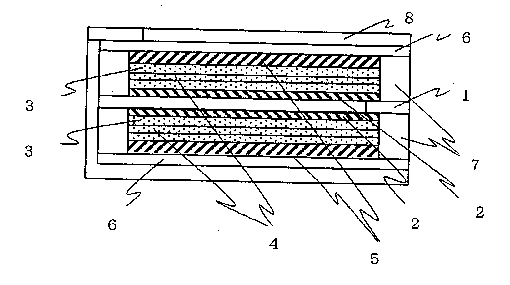
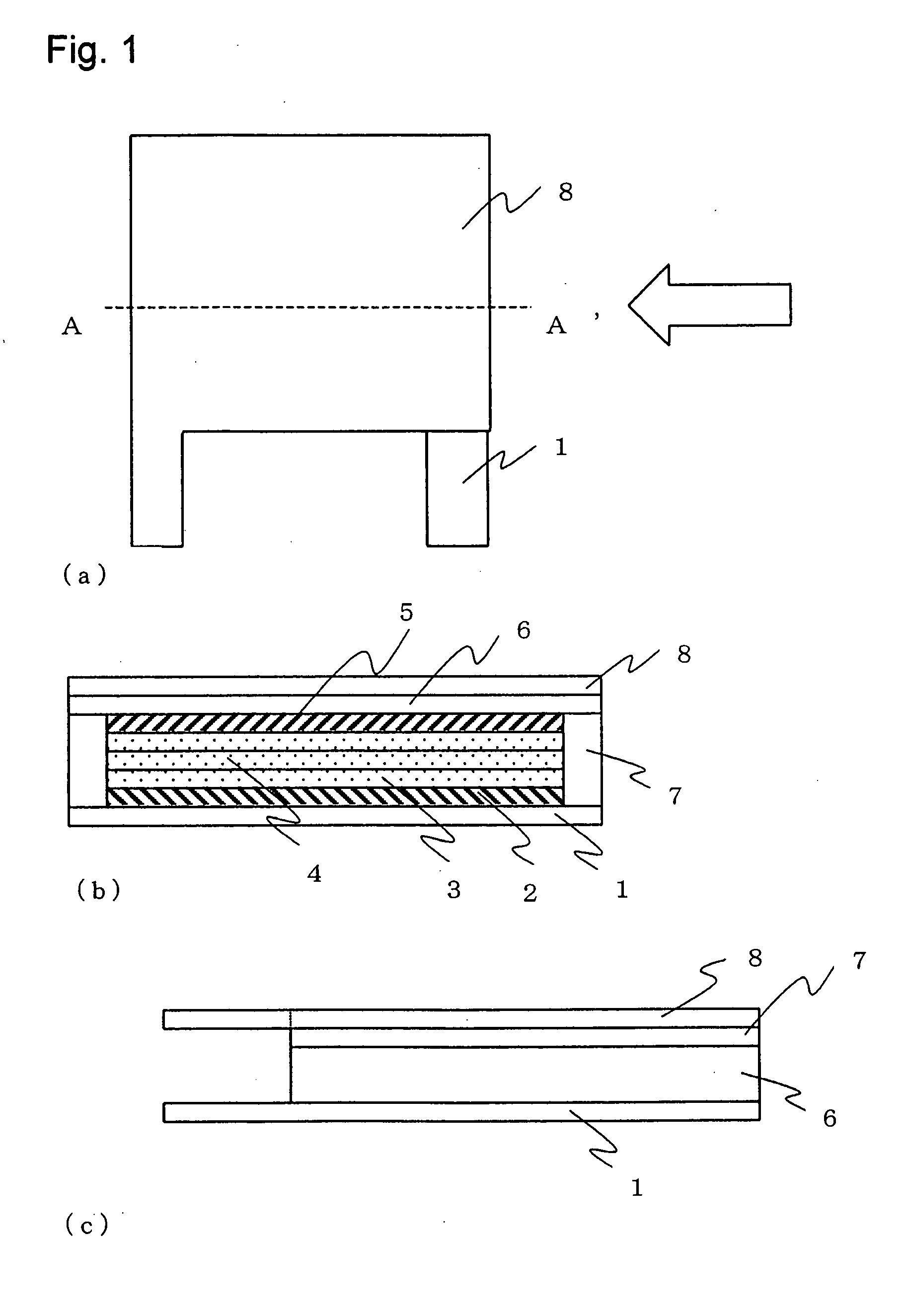
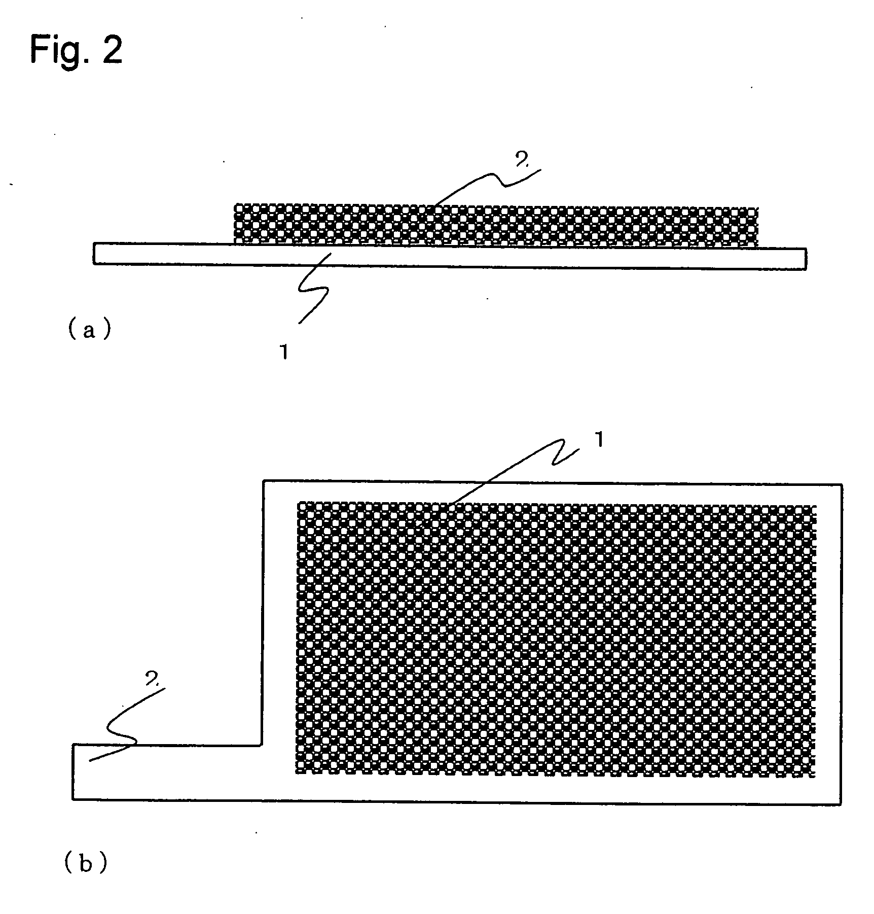
[0046] Referring to FIG. 4, the structure of the First Example of the present invention is described below. FIG. 4(a) is a schematic side view of First Example. Within a gasket 7 formed over both surfaces of the thin metal film 1, there are formed a porous anode substance 2 on the thin metal film, an active carbon layer 5 disposed to face that, and an electrolytic solution 3 and a separator 4, both of which are contained between the porous anode substance 2 and active carbon layer 5 opposite. An anode terminal is formed on the thin metal film, protruding.

[0047] Adjacent to each active carbon layers 5 a current collector 6 is formed within the gasket 7. On a cathode plate 8 which is formed to cover, together both current collectors 6 formed on opposite faces of the porous anode substrates 2 formed on both faces of the thin metal film, there is formed a cathode electrode.

[0048] The structure of the present example in which two capacitors are connected in parallel has, for the same a...

second example

[0054] Another example having the same structure as First Example but utilizing tantalum as a valve metal is described below.

[0055] With respect to a tantalum porous anode substance, after a paste of tantalum powder was first applied to a thickness of 0.25±0.05 mm, by the printing method onto both surfaces of a metal thin film of tantalum 34 mm long by 22 mm wide by 0.1 mm thick, sintering at 1100° C. in a vacuum of about 6.7×10⁻³ Pa (50 pTorr) was carried out for 30 minutes and thereby a metal porous material of tantalum was made. As for the paste of tantalum powder, tantalum powder with a specific surface area of 3.5 m2 / g, BC as a dispersing agent, an acrylic resin based binder as a binder and BPBG as a plasticizer were weighed and mixed so that their contents by weight in the paste of tantalum powder might become 81 wt. %, 11 wt. %, 4 wt. % and 4 wt. %, respectively.

[0056] In this way, a laminate type tantalum capacitor, 38.5 mm×26.5 mm×1 mm in dimensions, having a rated voltag...

third example

[0057] The same structure and the same manufacturing method as First Example were used herein, excepting that an electrode made of an active carbon layer on the cathode side in First Example was replaced by a porous cathode substance made of a sintered material of niobium which was used for the anode in First Example (only differing in a point that no oxide film was formed herein).

[0058] The sintered material of niobium has a smaller electrical resistance than the active carbon layer but the resistance component which effectively contributes to the ESR comes from the electrolytic solution so that the change of the cathode from the active carbon electrode to the metal electrode does not affect the ESR much.

[0059] Characteristics of an aluminium electrolytic capacitor, an electric double-layer capacitor and capacitors of the present examples, all having the same rated voltage, are listed in Table 1.

TABLE 1CapacitanceProductProductESR(mF)VolumeHeight(mΩ)(at 120 Hz)(cc)(mm)(at 100 k...


PUM


Abstract

The electrolytic capacitor and the electric double-layer capacitor both have difficulties to satisfy recent demands that the capacitor should have lower resistance, larger capacitance and moreover smaller size and thinner film thickness, altogether. The present invention provides a wet electrolytic capacitor which comprises a porous anode substance wherein at least a surface of a porous material made of a powder of a valve metal is an oxide film of the valve metal, a cathode formed of either an active carbon layer or a porous material made of a powder of a valve metal and an acid electrolytic solution contained between the porous anode substance and the cathode electrode.

Description

BACKGROUND OF THE INVENTION [0001] 1. Field of the invention [0002] The present invention relates to a wet electrolytic capacitor, and more particularly to a wet electrolytic capacitor having an anode wherein a valve metal is utilized for a porous anode substance. [0003] 2. Description of the Related Art [0004]FIG. 5(a) is a schematic view showing the structure of a wound type aluminium electrolytic capacitor. [0005]FIG. 5(b) is an exploded view of the wound type aluminium electrolytic capacitor. In structure, the wound type aluminium electrolytic capacitor has a capacitor element 16 of wound layers comprising an anode foil 14 and a cathode foil 13, separated by a layer of a separator 15, which is, together with an electrolytic solution 17, inserted into a metal case 18 and sealed with a sealing rubber. [0006] The anode foil 14 is made of a metallic aluminium foil and on its surface, an oxide film is formed as a dielectric. Since the electrostatic capacitance of the capacitor is pro...

Claims


Application Information

Patent Timeline
IPC IPC(8): H01G9/00H01G9/035H01G9/04H01G9/048H01G9/14H01G11/10H01G11/22H01G11/30H01G11/42H01G11/58H01G11/68
CPCH01G9/042H01G9/0425Y02E60/13H01G9/06H01G9/07H01G9/052
Inventor YOSHIDA, KATSUHIROSAIKI, YOSHIHIKOKAMISUKI, HIROYUKIMURATA, MASAHIRO
Owner TOKIN CORP
Why Eureka
Try Eureka