Tall V/STOL aircraft

a technology of v/stol aircraft and v/stol, which is applied in the direction of aircraft, vertical landing/take-off aircraft, transportation and packaging, etc., can solve the problems of limited payload, high cost of manufacture, operation and maintenance, and economic questionability of aircraft, so as to minimize the effect of ground effects, improve performance stability, and low disk loading

Inactive Publication Date: 2006-02-16
ALLEN NORMAN CARTER
View PDF13 Cites 27 Cited by
  • Summary
  • Abstract
  • Description
  • Claims
  • Application Information

AI Technical Summary

Benefits of technology

[0008] The present design avoids or moderates many of the problems of previous designs. The present invention significantly improves stability of performance in takeoff, decent and landing over previous airplanes. The current design utilizes tall fuselage structure(s) to mount tilting wing and engine assemblies. This configuration provides maximum clearance from the ground and uses large propeller(s) for low disk loading which minimizes ground effects; thereby, reducing dynamic ground pressures (less than one-half of current designs) and producing low velocity boundary layers in the area around the aircraft. The high placement of the engine(s) will reduce the likelihood of ingesting re-circulating hot gasses or kicked-up ground debris. The simplest configuration is shown in FIG. 1 and shows three views of a single tall fuselage of airfoil plan-form topped with a single wing having a tractor-mounted engine on its leading edge. The wing and engine can tilt about a horizontal axis to point in the direction of flight during cruise flight and point skyward during takeoff and landing. Attitude control of this airplane during cruise flight will be by the use of wing trailing edge aerodynamic surfaces functioning as ailerons to provide roll control and the upper and lower halves can also be independently deployed (on the right side or left side of the airplane) as drag “brakes” to control yaw. The trailing edge of the vertical fuselage also has an aerodynamic surface that acts as a conventional rudder in horizontal flight or can be deployed as a drag “brake” for pitch control or for slowing airplane descent. A single fuselage, single wing, twin-engine design is shown in FIG. 2 and will require use of a cross-shaft for engine failure safety. Control during hover, landing and takeoff for the two preceding configurations may require adding a conventional rudder and differential elevator embedded in the propulsion means slipstream at the trailing edge of the tilting wing. FIG. 3 shows a single fuselage, twin wing, four engine layout, which will also need cross-shafts. FIG. 4 shows a twin fuselage, twin wing, twin engine version which will not require use of a cross-shaft. This last one is the preferred embodiment design and will be discussed further below.

Problems solved by technology

These airplanes are economically questionable due to limited payload capability and the high cost of manufacture, operation and maintenance.
This is because there are many technical problems facing the V / STOL designer.
Jet engines of high specific horsepower are now available, but they exhibit very high velocity, hot-gas exhaust, which may damage or destroy a ground surface if it is in close proximity and at high incidence angles to the engine nozzle and this can result in the damage debris being circulated back into the engine inlet.
Turboprop power plants have cooler lower velocity exhaust streams, producing a lower velocity boundary layer on the ground, but pay a specific thrust penalty because of gearbox and propeller losses.
Present designs have multiple downwash columns which can produce “air fountain” interference effects that adversely interact with the airplane structure and result in control complications for the pilot,—and in severe cases, loss of the aircraft.
Rapid loss of lift can occur during STOL landing operations if powered re-circulating air gets trapped under a lifting surface.
Another risk is in rapid descending flight where one rotor, of an aircraft configuration like the V-22, encounters stall conditions and sends the aircraft into a violent rotation.
In some designs (e.g. V-22 Osprey) the downwash column in hover mode losses considerable lift because it impinges on the plan form of the cruise lift wing.
This cross shaft adds weight, complexity, and is itself a possible source of critical failure.
The XC-142 had to have a set of propellers installed on the tail to provide vertical force to offset severe pitch forces when the wings were tilted for slow / vertical flight and differential thrust on the outboard propellers and differential ailerons for control of pitch making piloting difficult and stressful.
The prop rotor design on airplanes like the V-22 is complicated by the requirement to incorporate cyclic as well as collective lift control into the propeller mechanism.
The cyclic control is necessary to provide control when operating in hover mode and increases the cost and risk of failure in these propellers.
The delay time for this cyclic control to respond to lateral disturbances may limit the conditions that this aircraft can deal with.
It is quite difficult in many of the previous aircraft designs for the pilot to maintain control during transitions of the lift systems from takeoff to cruise and then to landing.
All these previous designs are unstable near the ground during takeoff and landing, particularly in gusty wind conditions, and attitude control relies on slow, sometimes completely dedicated, lift augmentation generation systems making design and testing very difficult.
Some designs are unable to perform STOL flight while others cannot move themselves around on the ground.
The safety requirement for the crew and passengers when there is partial loss of power has overly complicated the design of these past and present airplanes.

Method used


Image

  • Tall V/STOL aircraft
  • Tall V/STOL aircraft
  • Tall V/STOL aircraft

Examples


Embodiment Construction

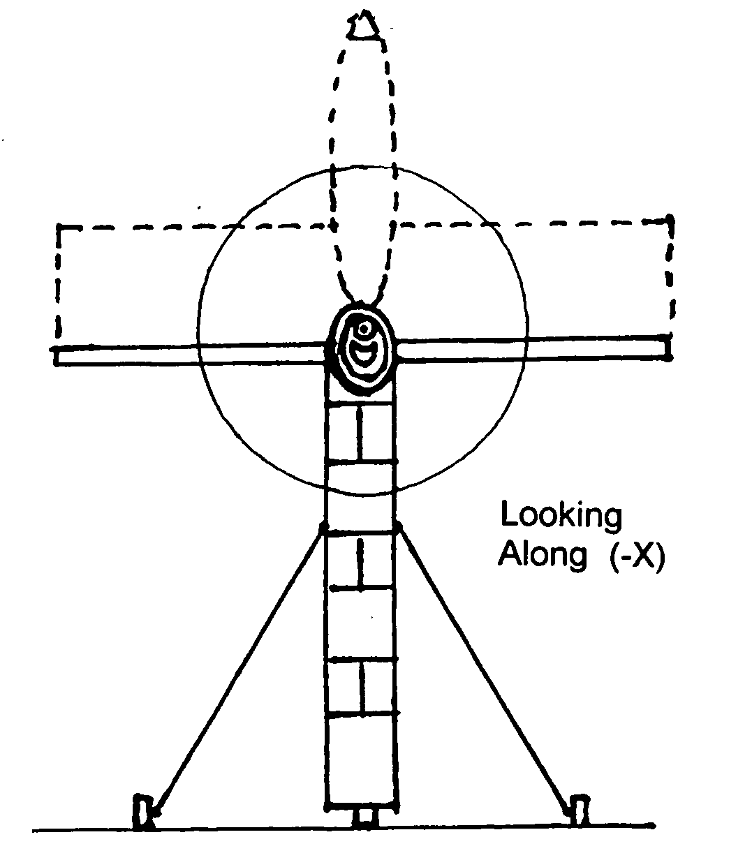
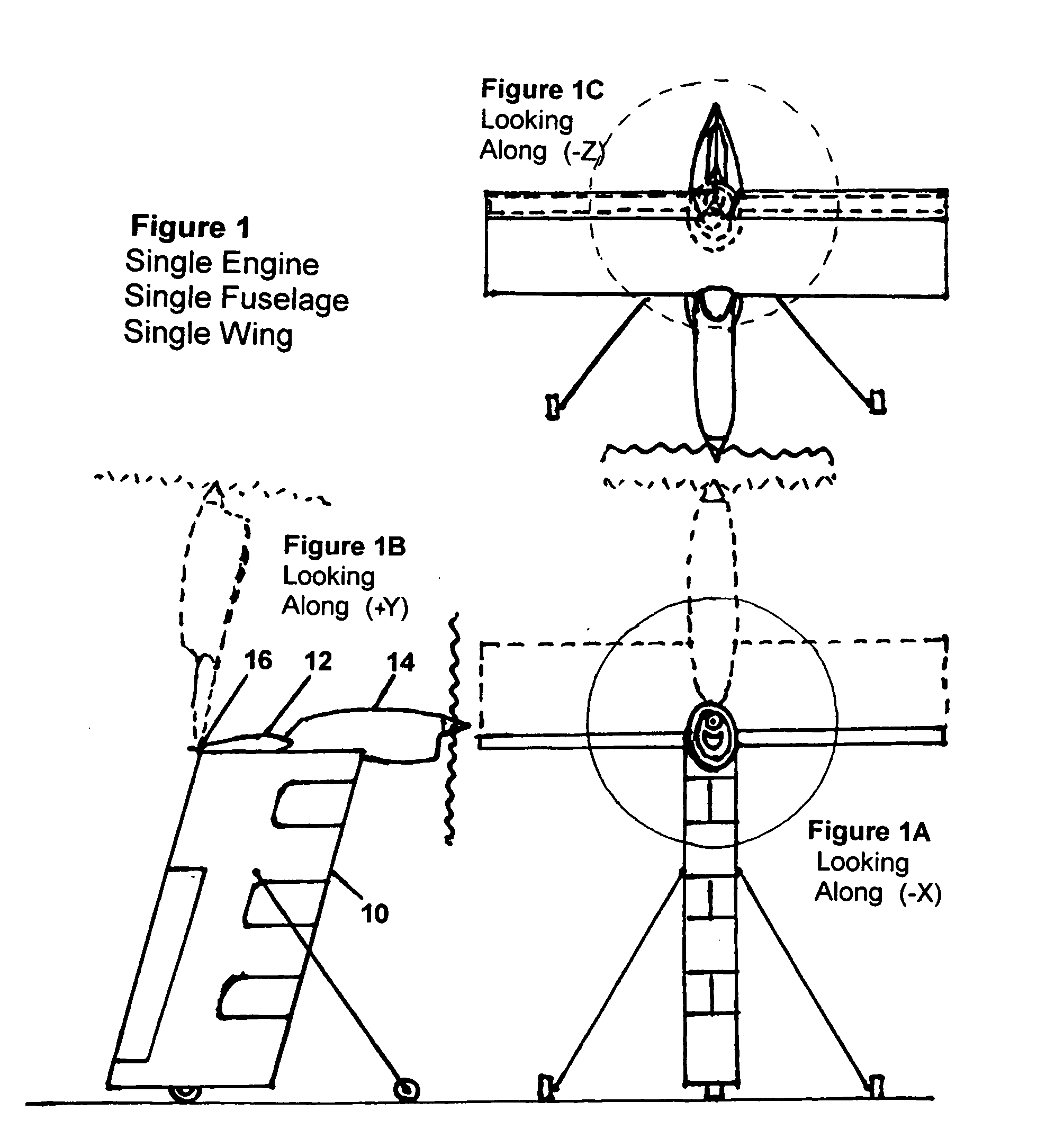
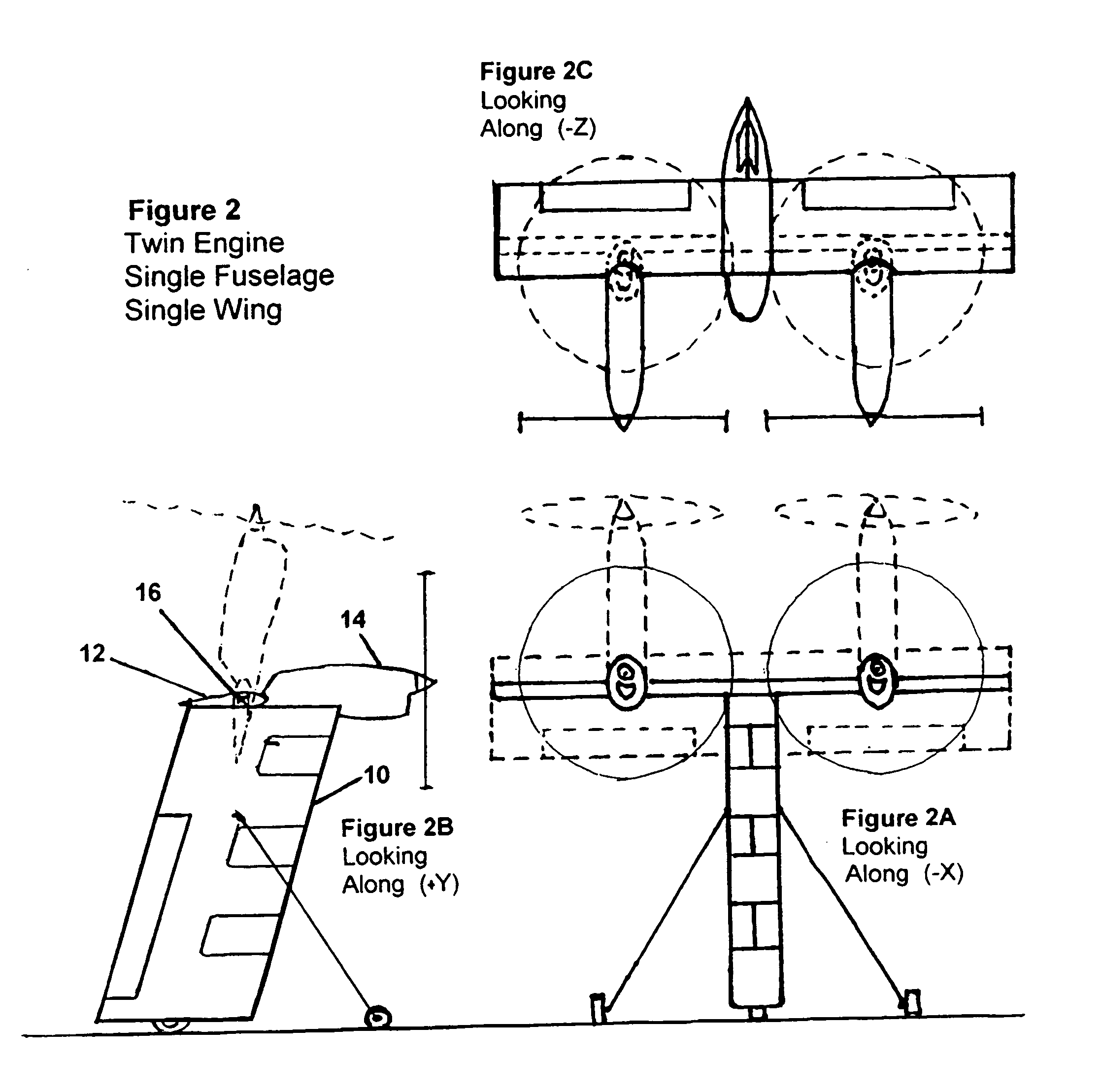
[0032] A vertical takeoff and landing (VTOL) airplane is described which is tall rather than long. This new configuration facilitates placing the propulsion engines at a maximum distance from the ground. It further allows improved motion and attitude control during takeoff and landing. The preferred embodiment, shown in FIG. 4, of the airplane consists of twin vertical cargo / passenger fuselage structures 10 having a thick airfoil shape in plan view. Near the top is a horizontal lifting wing 12 spanning the space between the vertical fuselage structures. A tractor propulsion engine 14 is attached to the leading edge of this lifting wing. The wing and engine can tilt as a unit around a horizontal axis 16 thereby changing the thrust and lift direction. The assembly tilts to point the engine skyward for takeoff and for landing touchdown. For cruise this assembly is tilted to point the engine so that the thrust is horizontal to the ground in the direction of cruise flight. Utilizing the ...


PUM


Abstract

A vertical or short takeoff and landing (V/STOL) airplane is described having a vertical form factor. Making the airplane tall has many advantages when operating in hover mode close to the ground. Several variations of the design are described. The preferred embodiment consists of two tall fuselage2 structures having an airfoil shape in plan view. As high above the ground as practical a “lift wing” spans the space between these fuselages. This wing may be equipped with lift augmentation systems to facilitate V/STOL flight. In the center of the span on the leading edge of the lift wing is placed a turboprop engine. Alternatively, the wing and attached engine can be made to tilt about a horizontal axis. For takeoff the wing will be tilted skyward. A second wing slightly below and behind the lift wing has a pusher engine located on the trailing edge. This lower wing and engine is also able to tilt about a horizontal axis parallel to the lift wing. During takeoff this lower engine is pointed downward toward the ground. This lower wing contains aerodynamic control surfaces to provide attitude and position control. Subsequent to liftoff the wings and engines tilt into a horizontal position to provide cruise lift and thrust. At the end of the flight the wings and attached engines are tilted back to provide vertical lift for hover, maneuvering, and soft landing.
2 “Fuselage” is used here even though it substantially differs from the conventional fuselage (and its French origins meaning, “spindle shaped”) since in plan view it is an airfoil shape of large thickness. It will be used here for lack of a better word. Think of fuselage as meaning “where the pilot, passengers and cargo are located”.

Description

BACKGROUND OF THE INVENTION [0001] The advantages of having a vertical and short takeoff and landing (V / STOL) airplane have been amply described in the aeronautical literaturei. A few of the more obvious reasons include economic use of the land in and around densely populated areas, reduced noise pollution, air service to suburban and rural communities as well as undeveloped countries, economic savings through flying more direct routes with more flexibility, and increased safety of flight operations. The justifications for use by the military are also strong. Despite all this, only two VTOL airplanes are now operational, the military Harrier and the Osprey V-22, which is just now coming into, the commercial market as the Bell-Boeing 609. These airplanes are economically questionable due to limited payload capability and the high cost of manufacture, operation and maintenance. The aeronautical community has worked on the V / STOL design challenge since the early 1950's. Despite conside...

Claims


Application Information

Patent Timeline
Patent Type & Authority Applications(United States)
IPC IPC(8): B64C27/22
CPCB64C5/06Y02T50/12B64C39/10B64C29/0033Y02T50/10
Inventor ALLEN, NORMAN CARTER
Owner ALLEN NORMAN CARTER
Why Eureka
Try Eureka