
Optical fiber for raman amplification

a technology of optical fiber and amplifier, which is applied in the direction of instruments, active medium shape and construction, lasers, etc., can solve the problems of unsatisfactory enhancement of raman gain correlated with these glass compositions, and little work on developing glasses suitable for raman amplification, etc., to achieve good thermal stability of glass, optical or thermal properties of optical fiber, the effect of broad emission bandwidth

Inactive Publication Date: 2006-02-16
PIRELLI & C
View PDF13 Cites 21 Cited by
  • Summary
  • Abstract
  • Description
  • Claims
  • Application Information

AI Technical Summary

Benefits of technology

"The present invention relates to a glass composition that can be used to manufacture optical fibers for Raman amplification. By simultaneously incorporating at least two different metal oxides into a tellurite glass, the optical and thermal properties of the glass can be optimized for enhancing the performance of the optical fiber for Raman amplification. The glass composition has been found to have a high maximum Raman gain and a broad emission bandwidth, which are important for achieving a good thermal stability and processability. The invention also provides a pump laser and an optical fiber for use in a Raman amplifier. The technical effects of the invention include improved optical and thermal properties of the optical fiber for Raman amplification, as well as better processability and higher efficiency of the pump laser."

Problems solved by technology

While many glass compositions have been proposed in connection with erbium doped fiber amplifiers, little work has been done in developing glasses suitable for Raman amplification.
The applicant has however observed that the enhancement of the Raman gain correlated with these glass compositions is not completely satisfactory.

Method used


Image

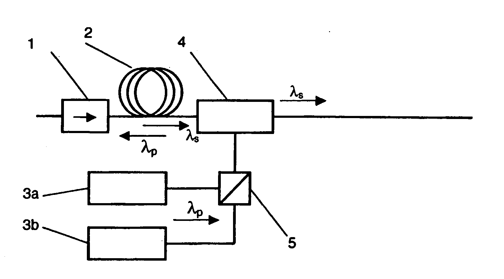
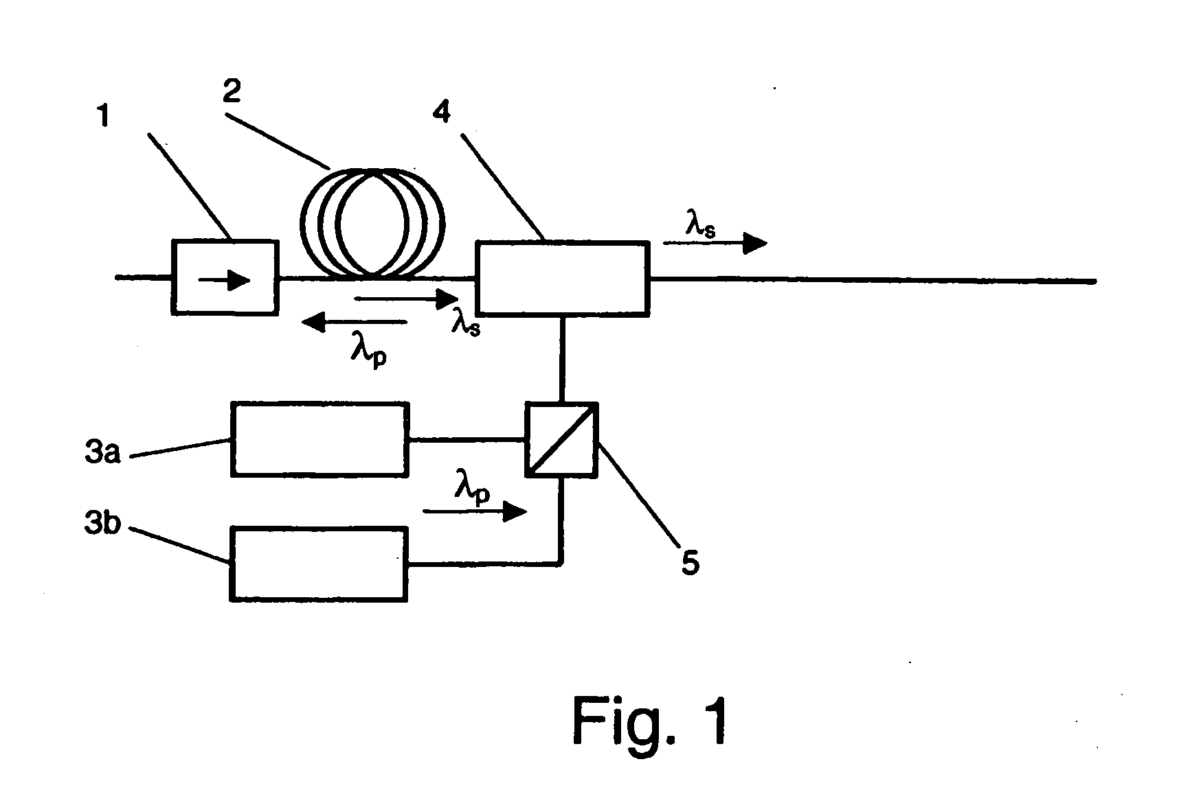
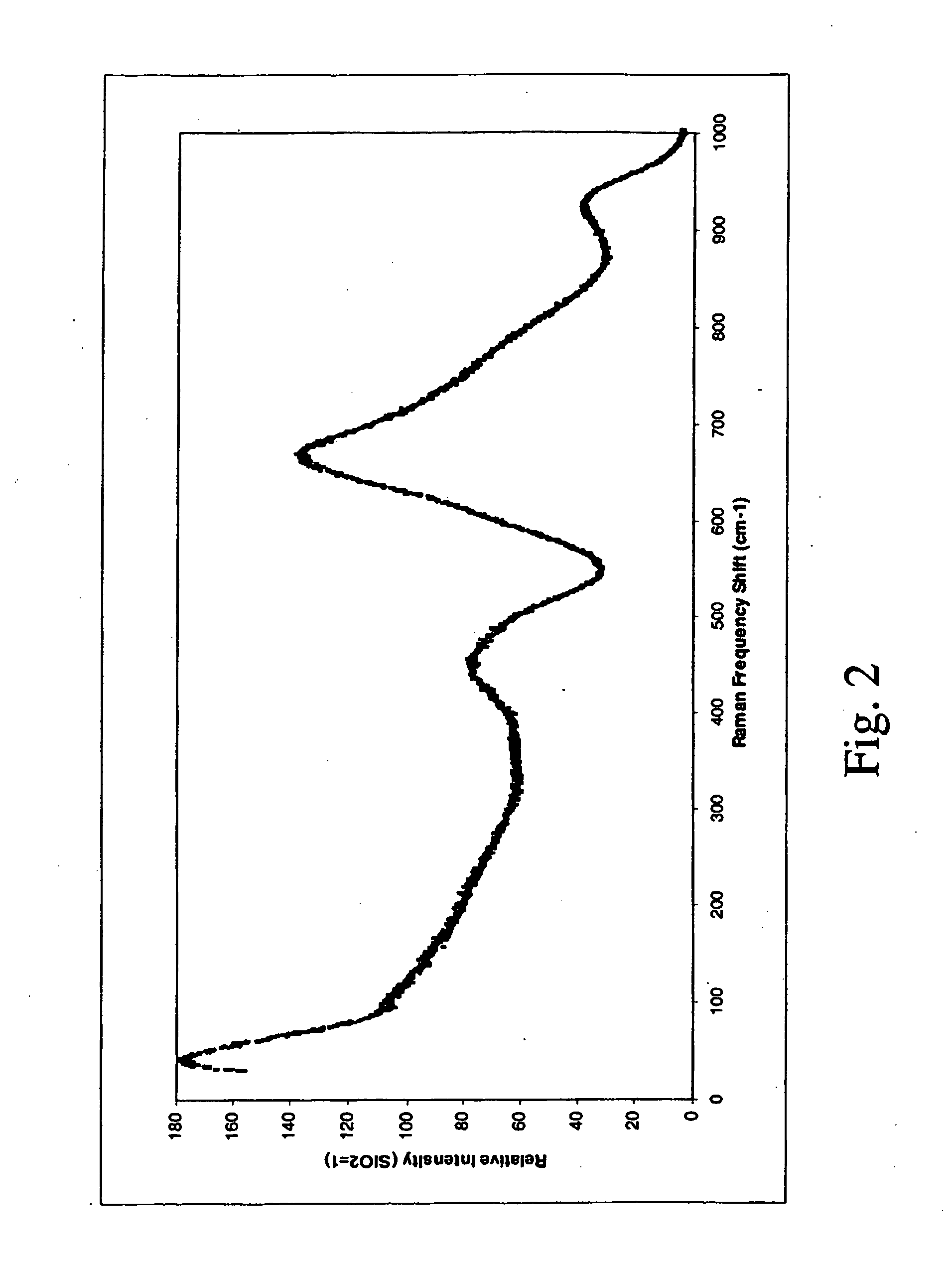
  • Optical fiber for raman amplification
  • Optical fiber for raman amplification
  • Optical fiber for raman amplification

Examples


example 1

[0095] Preparation of Glass Compositions

[0096] Glass compositions have been prepared by conventional melting techniques, by admixing the raw oxide materials in the prescribed molar amounts and charging the mixture in a Pt / Au crucible. A batch of about 50 g of each composition was melted in an electric furnace at temperature between 750° C. and 950° C. for 2 hours under the atmosphere of O2 / N2. Then the homogeneous melt was casted into a preheated brass mould for forming a glass bulk or perform. The glass was annealed below Tg for 4 hours.

[0097] The following table 1 shows the compositions which have been prepared, where the amount of each oxide is expressed as molar percentage over the total composition.

TABLE 1Glass compositionsTeO2NbO2.5WO3TiO2TN109010TN208020TN307030TW109010TW208020TW307030TT5955TT109010TT158515TNW721810TNT721810

[0098] A comparative glass composition (TZLB) comprising TeO2, ZnO, LiO2 and Bi2O3 in the respective percentage molar amount of 78%, 5%, 12% and 5% ha...

example 2

[0099] Thermal Stability of Glass Compositions

[0100] The above glass compositions have been subjected to DSC analysis, in order to determine the Tg and Tx of each composition, and thus the respective thermal stability index Tx-Tg.

[0101] For each glass composition, three bulk glass samples of around 20 mg were subjected to a DSC characterisation at a heating rate of 10° C. / min in N2 gas atmosphere. The measurement was performed using a DSC series Q10 apparatus (TA Instruments, U.S.A.).

[0102]FIG. 4 shows an example of a DSC plot of the following glass compositions: TNW, TN20 and TW10. The respective Tg and Tx values derivable from said plot, corresponding to the endothermic and to the (first) exothermic peak, respectively, are reported in the following table 2, together with the Tg and Tx values of the other glass compositions manufactured according to example 1. Table 2 further shows the relative Tx-Tg thermal stability index of said glass compositions.

TABLE 2Thermal stabilityTg...

example 3

[0104] Optical Properties of Glass Compositions

[0105] Raman measurements have been performed on polished thin slabs of the above glass compositions of about 1 mm thickness.

[0106] A confocal microscope optics has been used in order to focus well inside the sample, and in order to collect the scattered light from the same region. For this purpose, the same microscope optics were used both for the incident laser beam and for the collection of the Raman scattered light. The measurements have therefore been carried out in a backscattering geometry.

[0107] The Raman scattered light was analysed with a spectrometer and detected by a cooled CCD detector.

[0108] Two different linearly polarized laser sources were used, a frequency doubled Nd:YAG laser operating at 532 nm. As the green light of the 532 nm pump is relatively close to the absorption gap of the tellurite glasses, resonant Raman contribution could appear in the measured Raman spectrum. In order to check these contributions, the...


PUM

PropertyMeasurementUnit
mole percentageaaaaaaaaaa

Abstract

Raman amplifier having an optical fiber made of a tellurite glass is disclosed. The tellurite glass has at least two further metal oxides, the metals of said respective two oxides being selected from a first group of Nb, W, Ti, Tl, Ta, and Mo and from a second group of Nb, W, Ti, Pb, Sb, In, Bi, Tl, Ta, Mo, Zr, Hf, Cd, Gd, La, and Ba. The so obtained fiber has improved optical (Raman gain) and / or thermal (thermal stability index) properties. Alternatively, the tellurite based glass compositions of the fiber have at least one additional metal oxide, where the metal is selected among Nb, Ti, Tl, Ta, and Mo, the glass showing a particularly high Raman gain. The maximum Raman gain of these glasses is typically higher than 100 times of the maximum Raman gain of pure silica and the respective total cross-section of the Raman spectrum is typically greater than 100 times the total cross-section of pure silica, in the frequency measurement range of 200 cm−1 to 1080 cm−1.

Description

FIELD OF THE INVENTION [0001] The present invention relates to an optical fiber for Raman amplification and to a Raman amplifier comprising said optical fiber. In particular, said fiber is an optical fiber comprising a tellurite glass. BACKGROUND ART [0002] To compensate attenuation, optical communication systems often provide for amplification of optical signals at regular intervals along optical transmission fibers. The amplification may be produced by amplifiers based on rare-earth elements such as erbium or by amplifiers based on the Raman effect. [0003] Fiber Raman amplifiers are attracting great attention, because of their capability to increase the transmission capacity. Raman amplifiers offer several advantages, such as low noise, greater flexibility in choosing the signal wavelength and a flat and broad gain bandwidth. The greater flexibility in choosing the signal wavelength mainly depends on the fact that the Raman peak of a material, exploited for the amplification of th...

Claims


Application Information

Patent Timeline
Patent Type & Authority Applications(United States)
IPC IPC(8): H01S3/00G02B6/00C03C3/12C03C4/00C03C13/04G02F1/35H01S3/042H01S3/06H01S3/067H01S3/094H01S3/17H01S3/30
CPCC03C3/122C03C4/0071C03C13/048H01S3/302H01S3/094003H01S3/177H01S3/06754
Inventor DAI, GUOJUNTASSONE, FRANCESCO MARIA
Owner PIRELLI & C
Learn More