
Light-emitting element device, light-receiving element device, optical device, fluoride crystals, production method of fluoride crystals, and crucible

a technology of light-emitting elements and optical devices, which is applied in the direction of semiconductor lasers, crystal growth processes, instruments, etc., can solve the problems of reducing light-emitting efficiency or similar effects, and achieve excellent light transmissivity to short-wavelength light and high resistance to energy

Inactive Publication Date: 2006-02-23
JAPAN SCI & TECH CORP
View PDF15 Cites 11 Cited by
  • Summary
  • Abstract
  • Description
  • Claims
  • Application Information

AI Technical Summary

Benefits of technology

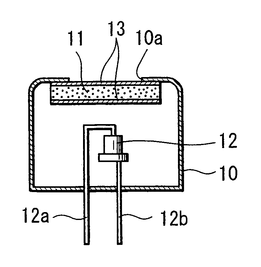
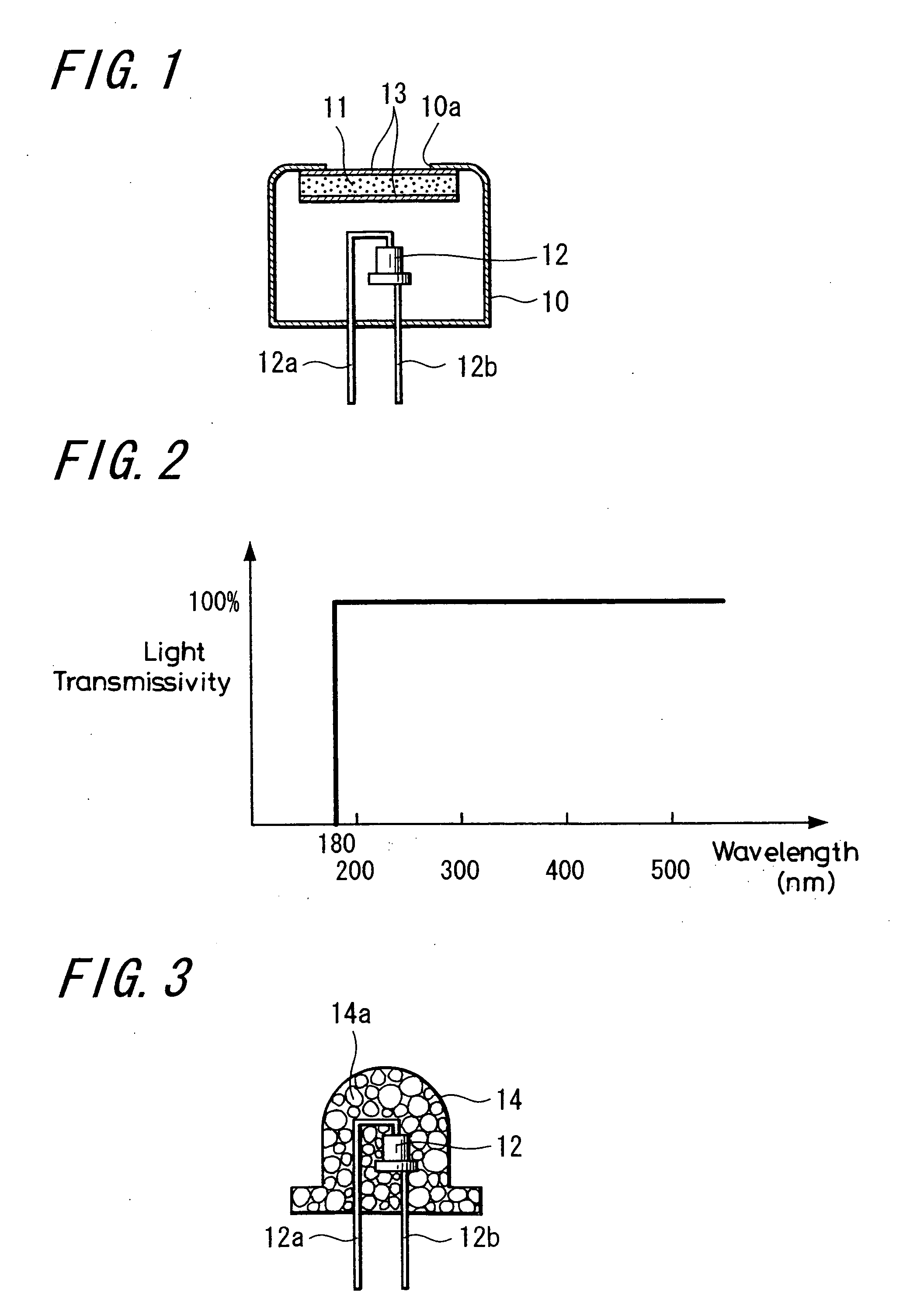
[0014] According to the above-described present invention, since a short-wavelength light-emitting element such as a blue light-emitting element is arranged inside a container which has a window with a window board formed of calcium fluoride crystals, this window board formed of calcium fluoride crystals is stable as far as 1400° C., is highly resistant to the energy of short-wavelength light, and has a good light transmissivity to short-wavelength light; therefore, it is possible to obtain a reliable, favorable light-emitting element device of short-wavelength light emission.
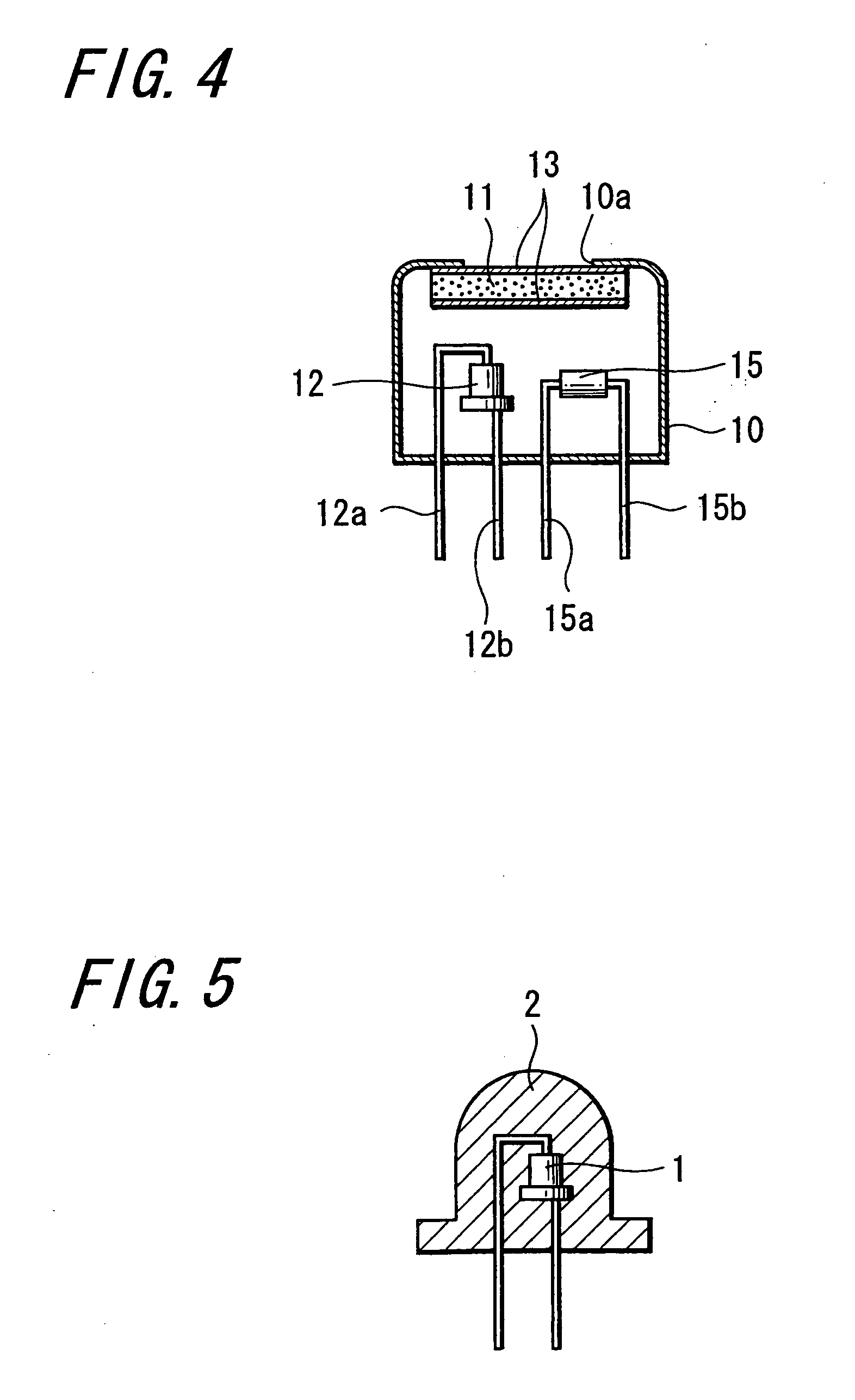
[0026] According to the above invention, since a short-wavelength light-emitting element such as an ultraviolet light-emitting element or blue light-emitting element and a light-receiving element are arranged inside a container which has a window with a window board formed of calcium fluoride crystals, this window board formed of calcium fluoride crystals is stable up to 1400° C., is highly resistant to the energy of short-wavelength light, and has an excellent light transmissivity to short-wavelength light; therefore, it is possible to obtain an optical device in which returning light of short-wavelength light emitted from this short-wavelength light-emitting element can be favorably detected by the light-receiving element.

Problems solved by technology

However, this short-wavelength light-emitting element 1 such as an ultraviolet light-emitting element or blue light-emitting element is high in the energy of light, which thus decomposes couplings of the epoxy resin 2 or the like covering this short-wavelength light-emitting element 1 and causes devitrification.
As a result, regarding a light-emitting element device using this short-wavelength light-emitting element 1, there has been such inconvenience in which light-emitting efficiency lowers noticeably or similar effects are caused, as it is used.

Method used


Image

  • Light-emitting element device, light-receiving element device, optical device, fluoride crystals, production method of fluoride crystals, and crucible
  • Light-emitting element device, light-receiving element device, optical device, fluoride crystals, production method of fluoride crystals, and crucible
  • Light-emitting element device, light-receiving element device, optical device, fluoride crystals, production method of fluoride crystals, and crucible

Examples


example 1

PRACTICE EXAMPLE 1

Ti-Added CaF2

[0112] Titanium-added calcium fluoride was produced.

[0113] A production method of titanium-added calcium fluoride is explained. FIGS. 6A, 6B and 6C show a carbon crucible which is used for producing fluoride crystals of the present invention. The diameter of a cavity 21 is one inch (2.54 cm). The carbon crucible was filled with powder that is the raw material for CaF2, and then was inserted in a vertical Bridgman furnace. When the raw material for CaF2 was put into the carbon crucible, 0.1 mol % of Ti was added to produce crystals. If a crystal orientation is decided, seed crystals are disposed on the bottom of the crucible. If a crystal orientation is not decided, it is not necessary to use seed crystals. Afterward, the inside of the electric furnace was made a vacuum of approximately 1×10⁻⁶ Torr, and with the vacuum being kept, the electric furnace was raised to 1450° C. in temperature. With this state, the temperature was kept for about two hours,...

example 2

PRACTICE EXAMPLE 2

TiF3-Added CaF2

[0117] Titanium fluoride added calcium fluoride was produced.

[0118] Practice Example 2 is the same as Practice Example 1 except that 0.1 mol % of TiF3 is added when the raw material for CaF2 is put into a carbon crucible.

[0119] Further, by means of a similar method to Practice Example 1, calcium fluoride to which 2 mol % of titanium fluoride had been added, and calcium fluoride to which 2 mol % of titanium fluoride and 0.5 mol % of zinc fluoride had been added were produced.

example 3

PRACTICE EXAMPLE 3

SrF2-Added CaF2

[0120] Strontium fluoride added calcium fluoride was produced.

[0121] Practice Example 3 is the same as Practice Example 1 except that 0.1 mol % of SrF2 is added when the raw material for CaF2 is put into a carbon crucible.

[0122] Further, by means of a similar method to Practice Example 1, calcium fluoride to which 0.2 mol %, 0.6 mol % or 2 mol % of strontium fluoride had been added, and calcium fluoride to which 2 mol % of strontium fluoride and 0.5 mol % of zinc fluoride had been added were produced.


PUM


Abstract

In the present invention, a short-wavelength light-emitting element such as an ultraviolet light-emitting element or blue light-emitting element is arranged in a container which has a window with a window board formed of calcium fluoride crystals. According to the present invention, it is possible to obtain a reliable light-emitting element device. Fluoride crystals of the present invention are ones which contain either metal or metal halide, or both of them. In a production method of fluoride crystals in which the cavity of a crucible is filled with raw material powder and this crucible is heated in a vertical Bridgman furnace, a production method of fluoride crystals of the present invention is the one in which the shortest diameter of a cross section of the cavity of the crucible is small. In a crucible, whose cavity is filled with raw material powder, heated in a vertical Bridgman furnace to produce fluoride crystals, a crucible of the present invention is the one in which the shortest diameter of a section of the cavity is small.

Description

REFERENCE TO RELATED APPLICATIONS AND INCORPORATION BY REFERENCE [0001] This application is a continuation-in-part of International Patent Application PCT / JP2003 / 016617 filed Dec. 24, 2003 and published as WO 2004 / 059750 on Jul. 15, 2004, which claims priority from Japanese Patent Application Number 2002-375426 filed Dec. 25, 2002. [0002] This application, and each application and patent mentioned in this document, and each document cited or referenced in each of the above applications and patents, including during the prosecution of each of the applications and patents (“application cited documents”) and any manufacturer's instructions or catalogues for any products cited or mentioned in each of the applications and patents and in any of the application cited documents, are hereby incorporated herein by reference. Furthermore, all documents cited in this text, and all documents cited or referenced in documents cited in this text, and any manufacturer's instructions or catalogues fo...

Claims


Application Information

Patent Timeline
IPC IPC(8): H01L33/00H01L29/24C30B29/12C30B29/64G02B1/02H01L31/02H01L31/0232H01L33/32H01L33/44H01L33/48H01L33/50H01L33/56H01S5/022
CPCG02B1/02H01L33/44H01L33/483H01S5/0222H01L2924/0002H01S5/02296H01L2924/00H01S5/02257H01L33/50
Inventor TERASHIMA, KAZUTAKANISHIMURA, SUZUKA
Owner JAPAN SCI & TECH CORP
Learn More