
Electromechanical machine-based artificial muscles, bio-valves and related devices

Inactive Publication Date: 2006-02-23
ORSEN
View PDF6 Cites 84 Cited by
  • Summary
  • Abstract
  • Description
  • Claims
  • Application Information

AI Technical Summary

Benefits of technology

[0023] The following summary of the invention is provided to facilitate an understanding of some of the innovative features unique to the embodiments and is not intended to be

Problems solved by technology

A physical ailment or condition which compromises the normal and healthy operation of the heart can therefore be particularly critical and may result in a condition which must be medically remedied.
Specifically, the natural heart, or rather the cardiac tissue of the heart, can fail for various reasons to a point where the heart can no longer provide sufficient circulation of blood for the body so that life can be maintained.
In utilizing artificial hearts and / or assist devices, a particular problem stems from the fact that the materials used for the interior lining of the chambers of an artificial heart are in direct contact with the circulating blood.
Such contact may enhance the undesirable clotting of the blood, may cause a build-up of calcium, or may otherwise inhibit the blood's normal function.
As a result, thromboembolism and hemolysis may occur.
Additionally, the lining of an artificial heart or a ventricular assist device can crack, which inhibits performance, even when the crack is at a microscopic level.
Moreover, these devices must be powered by a power source, which may be cumbersome and / or external to the body.
Such drawbacks have limited use of artificial heart devices to applications having too brief of a time period to provide a real lasting benefit to the patient.
Before replacing an existing organ with another, the substitute organ must be “matched” to the recipient, which can be, at best, difficult, time consuming and expensive to accomplish.
Furthermore, even if the transplanted organ matches the recipient, a risk exists that recipient's body will still reject the transplanted organ and attack it as a foreign object.
As currently used, skeletal muscle cannot alone typically provide sufficient and sustained pumping power for maintaining circulation of blood through the circulatory system of the body.
Typically, bypass systems of this type are complex and large, and, as such, are limited to short term use, such as in an operating room during surgery, or when maintaining the circulation of a patient while awaiting receipt of a transplant heart.
The size and complexity effectively prohibit use of bypass systems as a long-term solution, as they are rarely portable devices.
Furthermore, long-term use of a heart-lung machine can damage the blood cells and blood borne products, resulting in post surgical complications such as bleeding, thromboembolism function, and increased risk of infection.
Although somewhat effective as a short-term treatment, the pumping device has not been suitable for long-term use.
This “active filling” of the chambers with blood limits the ability of the pumping device to respond to the need for adjustments in the blood volume pumped through the natural heart, and can adversely affect the circulation of blood to the coronary arteries.
Furthermore, natural heart valves between the chambers of the heart and leaching into and out of the heart are quite sensitive to wall and annular distortion.
The movement patterns that reduce a chamber's volume and distort the heart walls may not necessarily facilitate valve closure (which can lead to valve leakage).
Another major obstacle with long term use of such pumping devices is the deleterious effect of forceful contact of different parts of the living internal heart surface (endocardium), one against another, due to lack of precise control of wall actuation.
However, it can compromise the integrity of the living endothelium.
Sphincter valves, however, tend to malfunction or lose range of operation.
Unfavorable conditions, however, often return or are sometimes not correctable using current treatments.
Erosion, probably from continuous high tonic pressure of inflated balloon in the urinary tract, can lead to infection and device failure.
Use of tendons can fail following trauma or because of arthritis.

Method used


Image

  • Electromechanical machine-based artificial muscles, bio-valves and related devices
  • Electromechanical machine-based artificial muscles, bio-valves and related devices
  • Electromechanical machine-based artificial muscles, bio-valves and related devices

Examples


Embodiment Construction

[0054] The particular values and configurations discussed in these non-limiting examples can be varied and are cited merely to illustrate at least one embodiment and are not intended to limit the scope thereof.

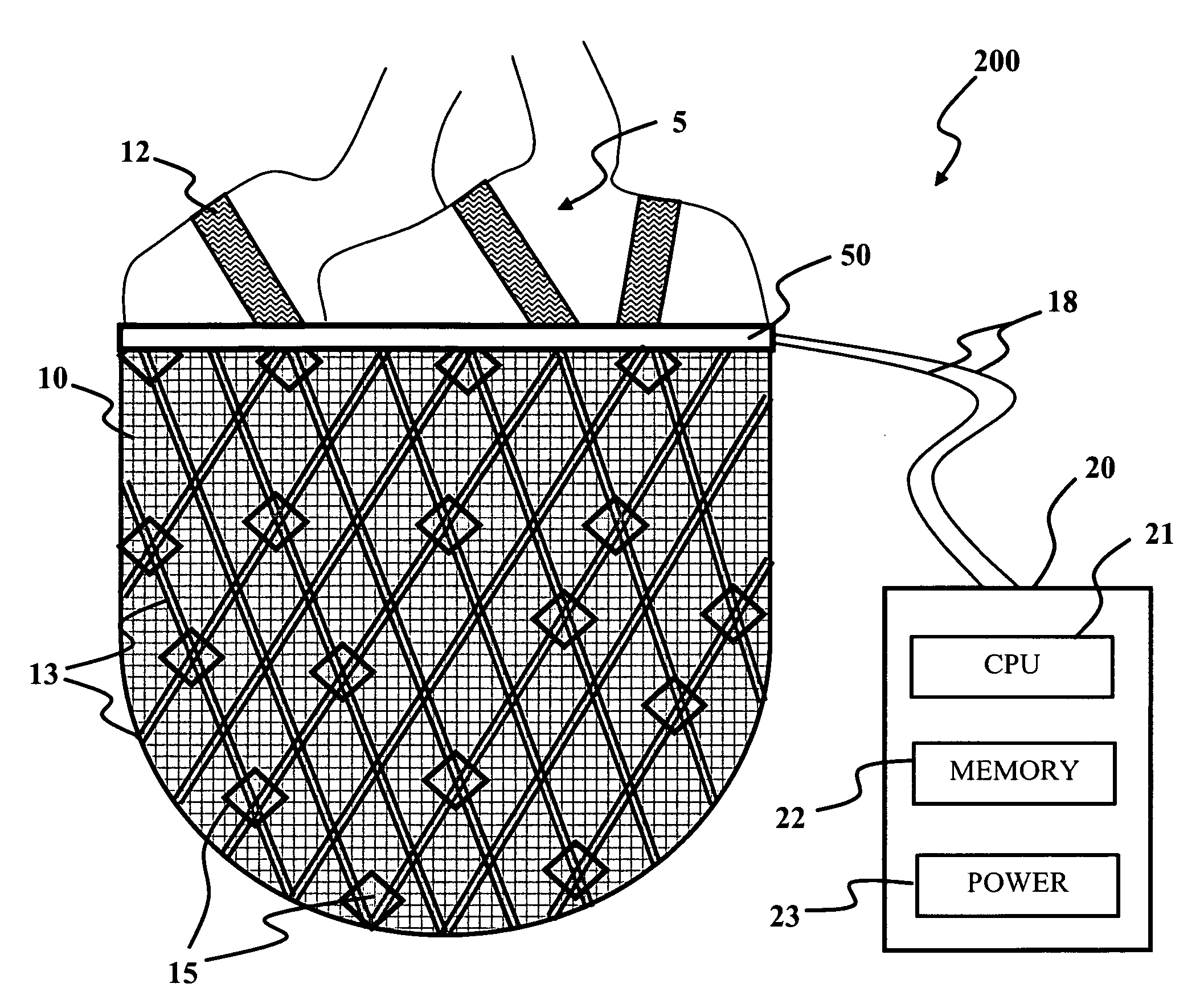
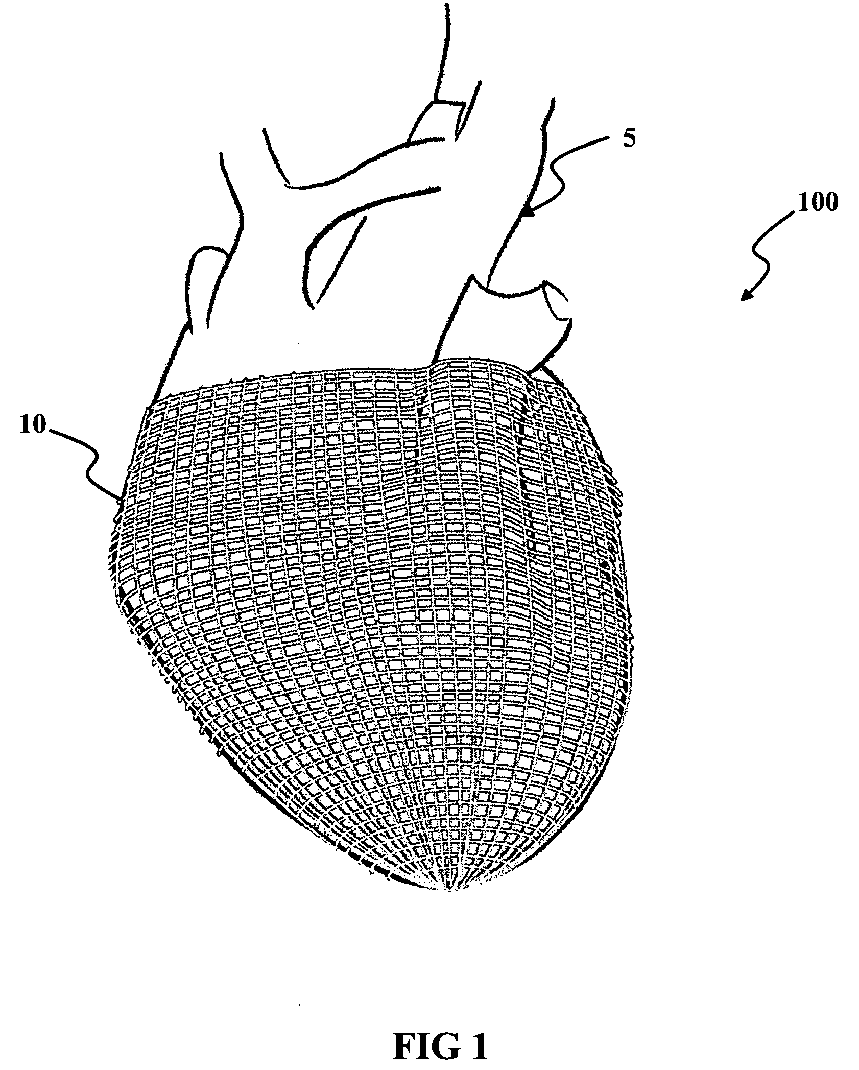
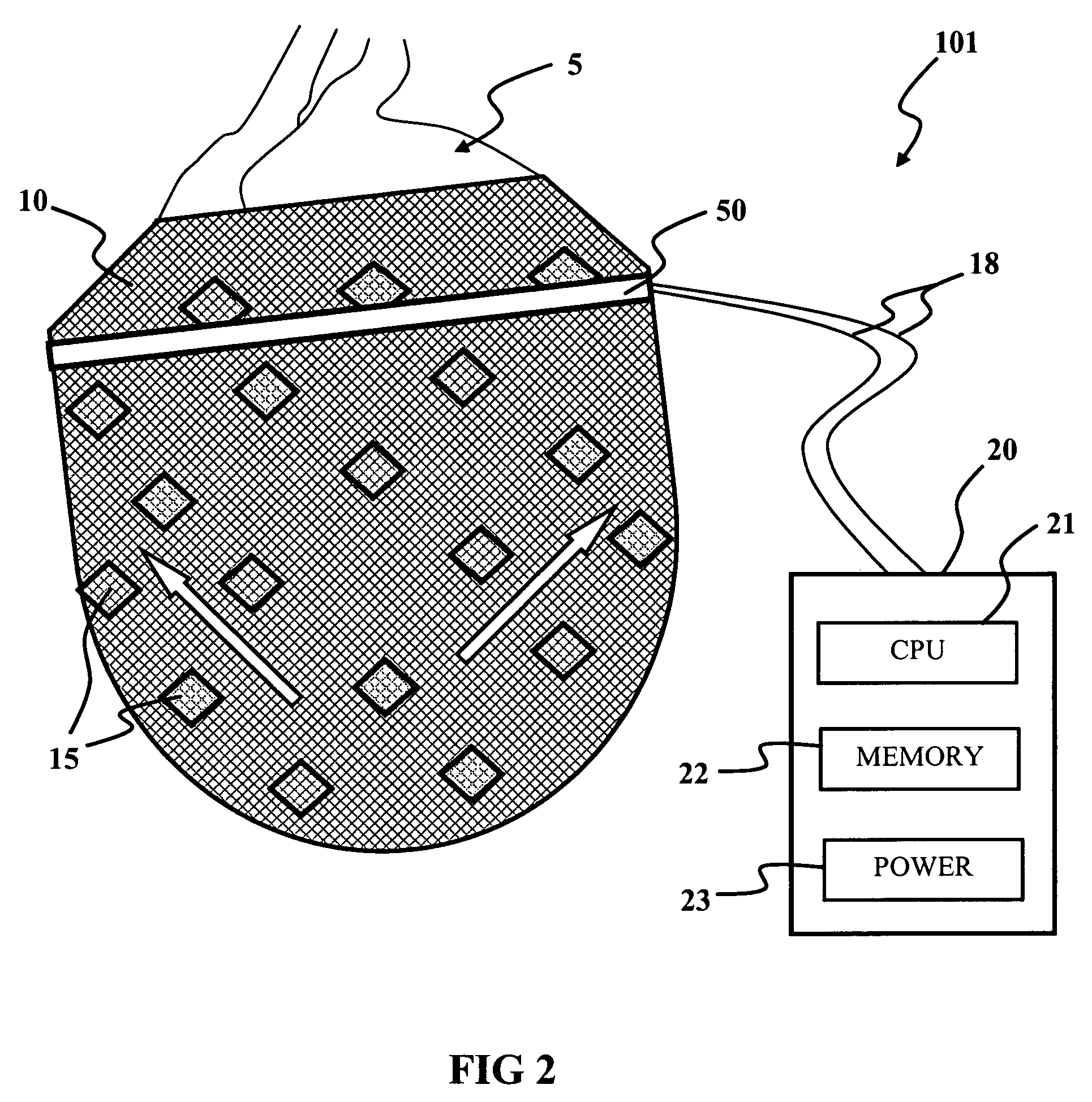
[0055] A natural human heart includes a lower portion comprising two chambers, namely a left ventricle and a right ventricle, which function primarily to supply the main pumping forces that propel blood through the circulatory system, including the pulmonary system (lungs) and the rest of the body, respectively. Hearts also includes an upper portion having two chambers, a left atrium and a right atrium, which primarily serve as entryways to the ventricles, and also assist in moving blood into the ventricles. The interventricular wall or septum of cardiac tissue separating the left and right ventricles is defined externally by an interventricular groove on the exterior wall of the natural heart. The atrioventricular wall of cardiac tissue separating the lower ventricular regio...


PUM


Abstract

A biological function assist apparatus composed an electromechanically-based system wrapped in protective coating and controlled by a controller, which also provides power to the electromechanically-based system. The electromechanically-based system can be formed as a mesh using MEMS or a larger electromechanically grid and wrapped around a failing heart, or the electromechanical system can be formed in a circle forming an artificial valve (e.g., sphincter). The electromechanically-based system can operate as a bone-muscle interface, thereby functioning in place of tendons.

Description

INVENTION PRIORITY [0001] This application is a continuation-in-part of U.S. patent application Ser. No. 10 / 923,357, entitled “Micro electromechanical machine-based ventricular assist apparatus,” which was filed with the United States Patent and Trademark Office on Aug. 20, 2004, and which is incorporated herein by reference herein in its entirety.TECHNICAL FIELD [0002] The embodiments are generally related to electro-mechanical systems. The embodiments are also related to artificial muscles. More particularly, embodiments are related to electromechanical-based artificial muscles, bio-valves and related devices. Embodiments are also related to devices for assisting natural human organs and body parts assisted by electromechanical-based devices. BACKGROUND OF THE INVENTION [0003] The natural human heart and accompanying circulatory system are critical components of the human body and systematically provide the needed nutrients and oxygen for the body. As such, the proper operation of...

Claims


Application Information

Patent Timeline
IPC IPC(8): A61M1/12A61F2/08A61M60/191A61M60/268A61M60/454A61M60/531A61M60/554A61M60/857
CPCA61B5/037A61M1/122A61B5/205A61B5/413A61F2/0036A61F2/08A61F2/2481A61F2002/0894A61F2250/0001A61M1/1037A61M1/1046A61M1/1068A61N2/02A61M1/1049A61M1/1055A61B5/1107A61M2205/0283A61M60/148A61M60/554A61M60/531A61M60/191A61M60/454
Inventor MASSEN, RICHARD J.ORTIZ, LUIS M.
Owner ORSEN
Learn More