Drill device and method for forming microconduits

a drilling device and microconductor technology, applied in the field of drilling devices and methods for forming microconductor, can solve the problems of common clinical problems such as the low rate of drug transport through the stratum corneum, and achieve the effect of reducing electrical impedance and allowing long-term drug diffusion

Active Publication Date: 2006-02-23
GALDERMA PHARMA
View PDF31 Cites 120 Cited by
  • Summary
  • Abstract
  • Description
  • Claims
  • Application Information

AI Technical Summary

Benefits of technology

[0035] As described above, one aspect of the invention is a method of painlessly removing the stratum corneum from the epidermis to permit long term diffusion of drugs into the body, which comprises the steps of drilling into a target area, monitoring an electrical impedance of the target area, stopping the drilling into the target area when a change in the electrical impedance is detected, thereby forming a microconduit, and placing a drug containing patch over the microconduit to permit long term diffusion of drugs into the body.
[0036] As described above, one aspect of the invention is a method of painlessly removing the stratum corneum from the epidermis in one or more locations to permit the reduction of the electrical impedance between an ECG or other electrode and the interior of the body for improved monitoring of body electrical signals, which comprises the steps of drilling into a target area, monitoring an electrical impedance of the target area, stopping the drilling into the target area when a change in the impedance is detected, thereby forming a microconduit, controlling the removal of the stratum corneum based upon a predetermined change in impedance, and attaching an ECG or other electrode to the skin over the site having the stratum corneum removed.

Problems solved by technology

However, the low rate of transport of therapeutic molecules through the stratum corneum remains a common clinical problem.

Method used


Image

  • Drill device and method for forming microconduits
  • Drill device and method for forming microconduits
  • Drill device and method for forming microconduits

Examples


experiment 1

Controlled Microconduit Drilling through Nails

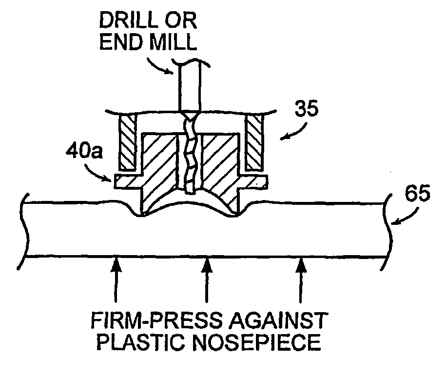
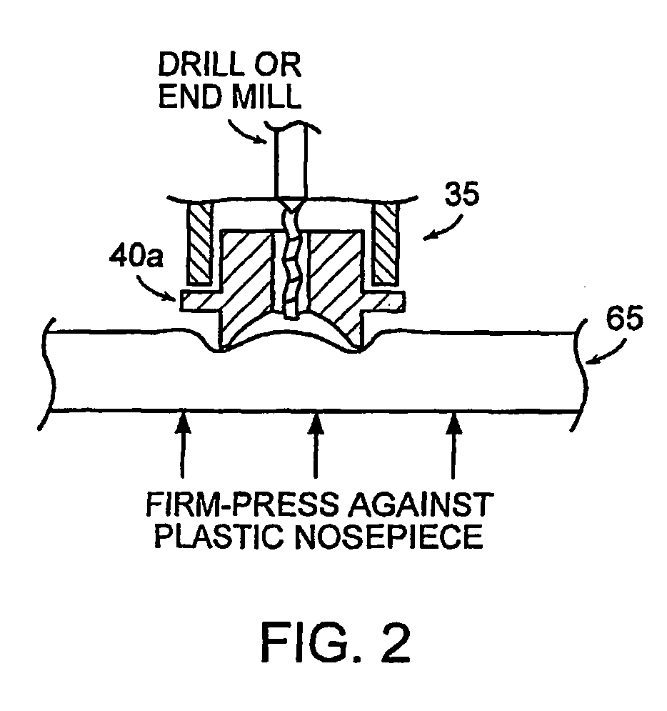
[0076] A number of experiments have been done with mechanically drilling holes through the nail. FIG. 7 shows a normally scised micro conduit that is 550-600 μm in diameter next to a 160 μm diameter micro conduit that was drilled in the overhang of a left ring finger using a 0.006 inches in diameter (150 μm) twist drill in a precision drill press.

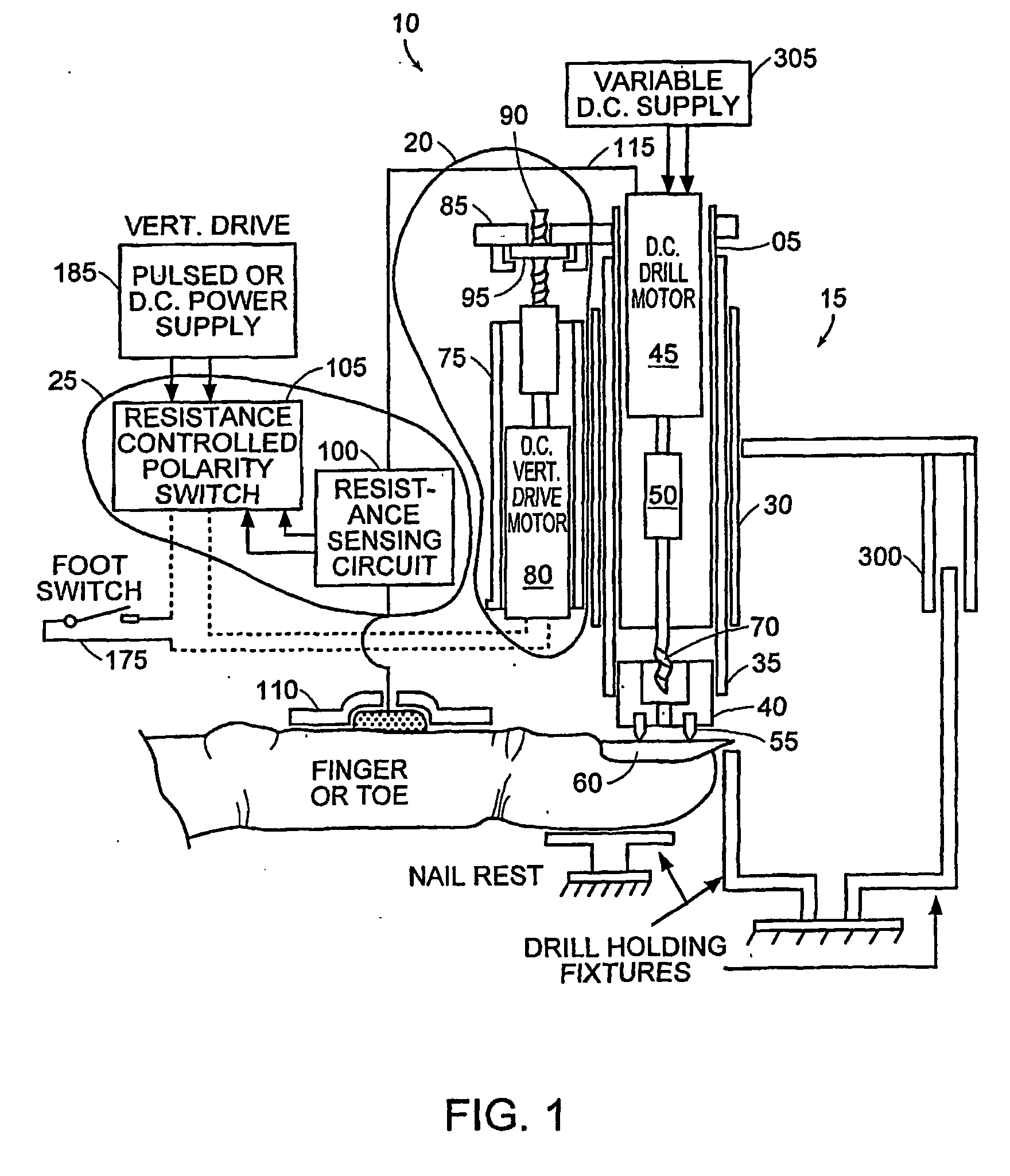
[0077] This approach has the advantages of making smaller size openings and permitting mechanical measurement of the drill depth below the surface of the nail via dial indicator monitoring. Also, depth determination into the nail bed can be determined through electrical resistance (impedance) measurements. An electrical contact to the quill of the drill press was established by using a ball bearing on a flex spring to permit real time resistance measurement with the rotating quill / chuck / drill. Thus, using an ECG electrode on the skin of the wrist as reported earlier, one can measure the elect...

experiment 2

Auto-Stop / Reverse of Microconduit Drilling

[0110] In order to move on to the Resistance Altimeter experiments, a comparator / relay circuit was fabricated to sense the ohmic resistance from the drill bit through the finger / toe to a nearby ECG patch adhered to the hand / foot. By using a relay and an amplifier / comparator chip, a potentiometer reference can be adjusted to essentially set the electrical resistance trigger ohmic value to flip the relay. The relay is hooked to a reversing relay (DPDT) to reverse the vertical drive motor. Thus, nail drilling is begun by stepping the vertical drive motor to move the drill motor down, pressing the spinning drill against the nail. As drilling proceeds, a depth is reached where the drill bit-to-body-to-ECG electrode electrical resistance begins to drop from about 3-6 meg ohms toward 100 K ohms, on down to the 10 / 20 K ohm range as the drill bit moves through the nail and into the increasingly living nail bed structure. At whatever predetermined e...

experiment 3

Drilling Dry vs. Wet Nail

[0138] A couple of test drillings began through subject's left hand pinky overhang which measures 16-17 mils thick. Using the same drill that was reported on after approximately 12 drillings, the first experiment was to simply drill through dry and see how many down pulses it took (the drill motor was running at 10 volts.). Drilling ended after 40 down pulses, the hole was partially through (est. 10 mils) and had a black bottom.

[0139] The next test was to use the same drill and hydrate the nail in the standard way (3 acetone rinses and blow-dry, 3 methanol rinses and blow-dry, 10 minute H2O soak). Again, although drilling in water, drilling ended after 50 down pulses. Here the hole was slightly deeper, not black on the bottom, but not through.

[0140] During both tests, it was noticed that the motor current never exceeded about 90 ma, where it usually pegs the 100 ma meter after each down step. This implies a really dull drill that is wearing, rather than ...


PUM


Abstract

The present invention relates to methods and devices for formation of microconduits in tissue, particularly using an impedance sensing drill to form microconduits. One embodiment of the invention is an impedance sensing drill comprising a drilling assembly, a control module, mechanically connected to the drilling assembly for controlling the depth of drilling by the drilling assembly; and a sensor, electrically connected to the drilling assembly and control module for detecting a change in an electrical impedance of a material being drilled. Another embodiment is a method of forming a microconduit in a material, which comprises the steps of drilling into the material, monitoring an electrical impedance of the material, and stopping the drilling into the material when a change in the impedance is detected, thereby forming microconduit.

Description

PRIORITY CLAIM [0001] This application claims priority from commonly owned copending U.S. Provisional Patent Application No. 60 / 457,208 filed 25 Mar. 2003. The disclosure of this application is hereby incorporated herein by reference.FIELD OF THE INVENTION [0002] The present invention relates to a drill device and methods of using the same for the formation of small openings, channels, or holes in tissue (or other materials). These holes are called “microconduits” herein. These microconduits are preferably formed using an impedance sensing drill. BACKGROUND OF THE INVENTION [0003] Transdermal drug delivery, as the term is used generally, refers to permeation of the stratum corneum, the tough outer barrier of the skin, by a pharmaceutically active molecule. The stratum corneum, the thin (approximately 10-20 μm) outer layer of the epidermis, is dead tissue containing both multilamellar lipid barriers, and tough protein-based structures. [0004] The epidermis, directly beneath the strat...

Claims


Application Information

Patent Timeline
Patent Type & Authority Applications(United States)
IPC IPC(8): A61M31/00A61BA61B5/05A61B5/053A61B17/00A61B17/20
CPCA61B5/053A61B17/205A61B2017/00026A61B17/1695A61N1/30A61N1/327A61B2017/00747A61M37/0076
Inventor HERNDON, TERRY O.
Owner GALDERMA PHARMA
Why Eureka
Try Eureka