
Organic electroluminescence device and anthracene derivative

an electroluminescence device and anthracene technology, applied in the field of organic electroluminescence devices and anthracene derivatives, can solve the problems of not being able to actually synthesize compounds as light emitting materials, and achieve the effect of great light emission efficiency

Active Publication Date: 2006-03-02
IDEMITSU KOSAN CO LTD
View PDF14 Cites 276 Cited by
  • Summary
  • Abstract
  • Description
  • Claims
  • Application Information

AI Technical Summary

Benefits of technology

[0005] The present invention has been made to overcome the above problems and has an object of providing an EL device exhibiting a great efficiency of light emission and has a long life and an anthracene derivative providing the device.
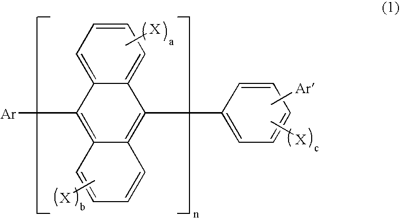
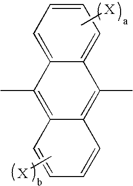
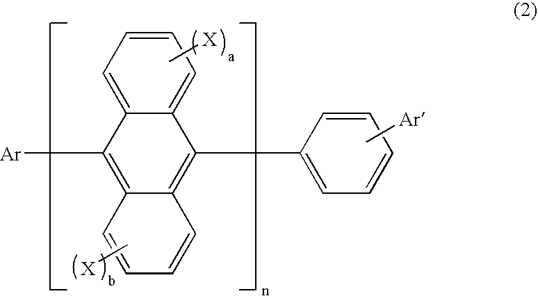
[0006] As the result of intensive studies by the present inventors to achieve the above object, it was found that an EL device exhibiting a great efficiency of light emission and has a long life could be obtained when a compound having an anthracene structure having a specific asymmetric structure represented by general formula (1) or (2) shown below is used as the light emitting material of an organic EL device. The present invention has been completed based on this knowledge.
[0089] In the organic EL device of the present invention, it is preferable that a layer of a chalcogenide, a metal halide or a metal oxide (this layer may occasionally be referred to as a surface layer) is disposed on the surface of at least one of the pair of electrodes prepared as described above. Specifically, it is preferable that a layer of a chalcogenide (including an oxide) of a metal such as silicon and aluminum is disposed on the surface of the anode at the side of the light emitting layer, and a layer of a metal halide or a metal oxide is disposed on the surface of the cathode at the side of the light emitting layer. Due to the above layers, stability in driving can be improved.
[0091] In the organic EL device of the present invention, it is preferable that a mixed region of an electron transfer compound and a reducing dopant or a mixed region of a hole transfer compound and an oxidizing dopant is disposed on the surface of at least one of the pair of electrodes prepared as described above. Due to the mixed region disposed as described above, the electron transfer compound is reduced to form an anion, and injection and transportation of electrons from the mixed region into the light emitting medium can be facilitated. The hole transfer compound is oxidized to form a cation, and injection and transportation of holes from the mixed region into the light emitting medium is facilitated. Preferable examples of the oxidizing dopant include various types of Lewis acid and acceptor compounds. Preferable examples of the reducing dopant include alkali metals, compounds of alkali metals, alkaline earth metals, rare earth metals and compounds of these metals.
[0109] A cathode is formed on the electron injecting layer formed above in the last step, and an organic EL device can be obtained. The cathode is made of a metal and can be formed in accordance with the vacuum vapor deposition process or the sputtering process. It is preferable that the vacuum vapor deposition process is used in order to prevent formation of damages on the lower organic layers during the formation of the film.

Problems solved by technology

However, these derivatives have not been actually synthesized, and the evaluation of these compounds as the light emitting material has not been made.

Method used


Image

  • Organic electroluminescence device and anthracene derivative
  • Organic electroluminescence device and anthracene derivative
  • Organic electroluminescence device and anthracene derivative

Examples


synthesis example 2

Synthesis of 2-(4-bromophenyl)naphthalene

[0117] Under the atmosphere of argon, a solution prepared by dissolving 7.1 g of 2-naphthaleneboric acid (manufactured by TOKYO KASEI Co., Ltd.), 12.9 g of 4-iodobromobenzene (manufactured by TOKYO KASEI Co., Ltd.), 0.6 g of tetrakis(triphenylphosphine)palladium(0) (manufactured by TOKYO KASEI Co., Ltd.) and 12.7 g of sodium carbonate (manufactured by HIROSHIMA WAKO Co., Ltd.) into 60 ml of water was placed into a 300 ml flask, and the resultant mixture was stirred for 24 hours while being heated under the refluxing condition. After the reaction was completed, the reaction mixture was cooled to the room temperature, and formed crystals were separated by filtration. The obtained crystals were recrystallized from toluene, and 9.0 g of crystals were obtained

[0118] Since m / z=284 in FD-MS of the obtained compound, which corresponded to C16H11Br=283, the compound was identified to be 2-(4-bromophenyl)naphthalene (the yield: 77%).

synthesis example 3

Synthesis of 3-(4-bromophenyl)fluoranthene

[0119] Under the atmosphere of argon, 62 g of fluoranthene and 250 ml of dehydrated DMF (manufactured by HIROSHIMA WAKO Co., Ltd.) were placed into a 500 ml flask and heated at 80° C. After the material was dissolved, 60 g of N-bromosuccinimide (manufactured by HIROSHIMA WAKO Co., Ltd.) was added at 50° C., and the resultant mixture was stirred for 2 hours. After the reaction was completed, the reaction solution was poured into 500 ml of purified water, and formed crystals were separated by filtration. The separated crystals were purified in accordance with the column chromatography, and 10.5 g of crystals were obtained.

[0120] Under the atmosphere of argon, 10.0 g of the crystals obtained above, 120 ml of dehydrated ether (manufactured by HIROSHIMA WAKO Co., Ltd.) and 120 ml of dehydrated toluene (manufactured by HIROSHIMA WAKO Co., Ltd.) were placed into a 500 ml flask, and the resultant mixture was cooled at −0.64° C. in a dry ice bath. ...

synthesis example 4

Synthesis of 10-(3-fluoranthenyl)anthracene-9-boric acid

[0123] Under the atmosphere of argon, a solution prepared by dissolving 7.85 g of 3-fluorantheneboric acid, 6.84 g of 9-bromoanthracene (manufactured by TOKYO KASEI Co., Ltd.), 0.6 g of tetrakis-(triphenylphosphine)palladium(0) (manufactured by TOKYO KASEI Co., Ltd.), 50 ml of toluene (manufactured by HIROSHIMA WAKO Co., Ltd.) and 8.5 g of sodium carbonate (manufactured by HIROSHIMA WAKO Co., Ltd.) into 50 ml of water was placed into a 300 ml flask, and the resultant mixture was stirred for 24 hours while being heated under the refluxing condition. After the reaction was completed, the reaction mixture was cooled to the room temperature, and formed crystals were separated by filtration. The obtained crystals were recrystallized from toluene, and 4.6 g of crystals were obtained

[0124] Under the atmosphere of argon, 4.5 g of the crystals obtained above and 100 ml of dehydrated DMF (manufactured by HIROSHIMA WAKO Co., Ltd.) were ...


PUM

PropertyMeasurementUnit
Timeaaaaaaaaaa
Timeaaaaaaaaaa
Timeaaaaaaaaaa

Abstract

An organic electroluminescence device which comprises a cathode, an anode and an organic thin film layer comprising at least one layer comprising a light emitting layer and disposed between the cathode and the anode, wherein at least one layer in the organic thin film layer comprises an anthracene derivative having a specific structure singly or as a component of a mixture, and an anthracene derivative having a specific asymmetric structure and providing an organic electroluminescence device exhibiting a great efficiency of light emission and having a long life, are provided.

Description

TECHNICAL FIELD [0001] The present invention relates to an organic electroluminescence device and an anthracene derivative and, more particularly, to an electroluminescence device exhibiting a great efficiency of light emission and having a long life and an anthracene derivative providing the device. BACKGROUND ART [0002] An organic electroluminescence (“electroluminescence” will be occasionally referred to as “EL”, hereinafter) device is a spontaneous light emitting device which utilizes the principle that a fluorescent substance emits light by energy of recombination of holes injected from an anode and electrons injected from a cathode when an electric field is applied. Since an organic EL device of the laminate type driven under a low electric voltage was reported by C. W. Tang of Eastman Kodak Company (C. W. Tang and S. A. Vanslyke, Applied Physics Letters, Volume 51, Pages 913, 1987), many studies have been conducted on organic EL devices using organic materials as the constitu...

Claims


Application Information

Patent Timeline
IPC IPC(8): H01J1/88C07C13/66C07C15/28C09K11/06H01L51/00H01L51/30H05B33/14
CPCC07C13/66H01L51/0072C07C43/20C07C43/257C07C2103/24C07C2103/26C07C2103/40C07C2103/50C09K11/06C09K2211/1011C09K2211/1014H01L51/0052H01L51/0058H01L51/0059H01L51/0081H01L2251/308H05B33/14Y10S428/917H01L51/0067C07C15/28C07C2603/24C07C2603/26C07C2603/40C07C2603/50H10K85/626H10K85/615H10K85/631H10K85/324H10K2102/103H10K50/11H10K85/622H10K85/654H10K85/6572H10K50/81H10K50/82C09K2211/1007
Inventor IKEDA, HIDETSUGUIDO, MOTOHISAFUNAHASHI, MASAKAZU
Owner IDEMITSU KOSAN CO LTD
Learn More