Method and apparatus for heat treatment of powder of fine carbon fiber

Inactive Publication Date: 2006-03-02
MITSUI & CO LTD
View PDF3 Cites 25 Cited by
  • Summary
  • Abstract
  • Description
  • Claims
  • Application Information

AI Technical Summary

Benefits of technology

[0034] According to the process of the present invention, a crucible or a molding apparatus by compaction-filling is not required, and therefore the equipment cost is markedly inexpensive as compared with those in conventional heat

Problems solved by technology

It is known that the above as-grown carbon fibers and carbon nanotubes in which the unreacted organic compounds and polymers are adsorbed on surfaces cause troubles in a treating step when they are processed into composite materials and that they have inferior crystallinity so that heat treatment is required in order to remove volatile components to improve the crystallinity.
Accordingly, the actual industrialization thereof requires an enormous cost of facilities and energy.
However, the following problems are involved in those processes.
1) The vessel is a graphite crucible, and a graphite crucible having a large volume is required for treatment in a large quantity, so that the cost therefor is increased.
2) If pressure is not applied when filling into the vessel, the amount to be filled is extremely small, and the efficiency is inferior.
5) The filling device is large-scaled, and a cost for the device is required.
6) Taking the facility cost and the operation cost into consideration, the product is commercially expensive.
B) Problems in a Compaction-Molding Process
3) It is difficult to apply even pressure to the inside of a fiber aggregate in a powder compressing operation, and molding is not easy.
4) The molded article has a low density and is expanded due to elasticity, and therefore the molded article does

Method used


Image

  • Method and apparatus for heat treatment of powder of fine carbon fiber
  • Method and apparatus for heat treatment of powder of fine carbon fiber
  • Method and apparatus for heat treatment of powder of fine carbon fiber

Examples


example 1

Batch Process Equipment

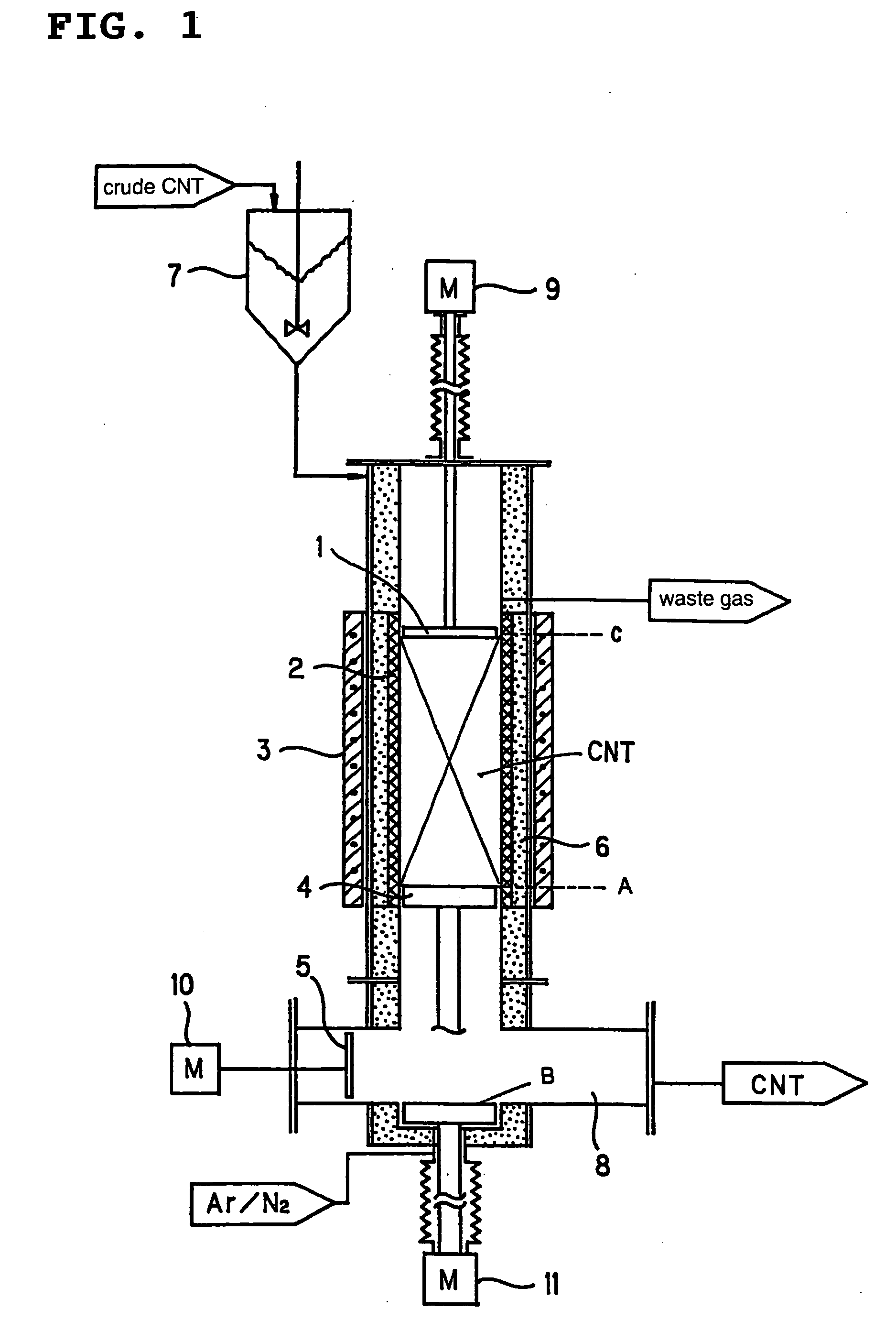
[0049] Carried out by equipment shown in FIG. 1.

[0050] It is a vertical batchwise heating furnace having an inner diameter of 200 mm, and it is equipped at an upper part with a charging device (7) for as-grown fine carbon fibers to be subjected to heat treatment and a driving mechanism (9) for moving upward and downward a push-in plate (1) for pushing in and scratching off the above material. A discharge port for a waste gas is disposed at an upper part of a heating part. Disposed at the lower part is a collecting mechanism comprising a collecting tank (8) for the above fine carbon fibers after subjected to heat treatment, a discharge plate (5) for the carbon fibers subjected to heat treatment and a driving mechanism (10) therefor and a holding plate (4) for preventing the untreated carbon material from leaking and a driving mechanism (11) therefor. The above holding plate is reciprocated alternatively between a position of an end A of a soaking part and a ...

example 2

Continuous Process Equipment

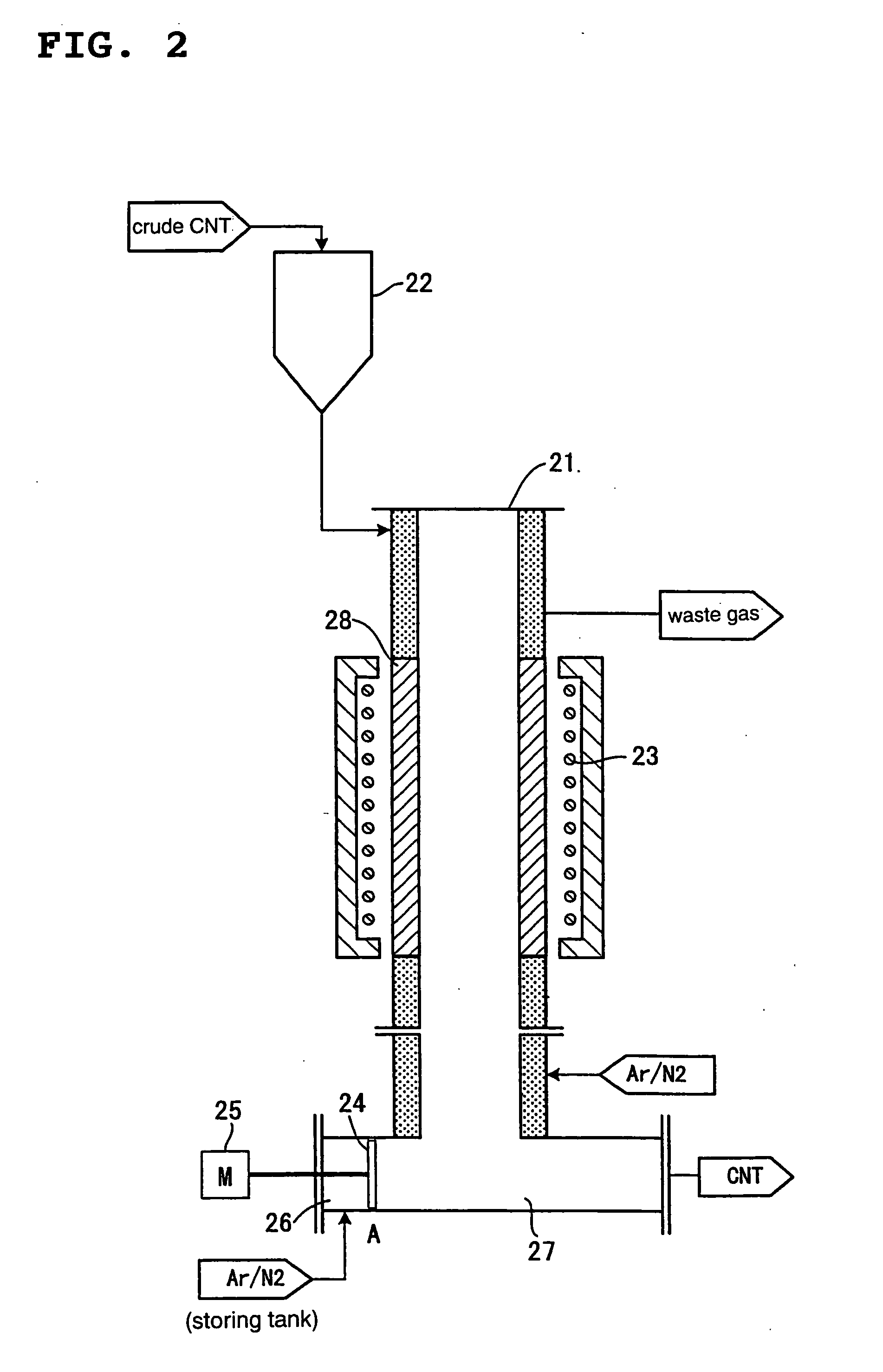
[0073] Carried out using equipment shown in FIG. 2.

[0074] It is a continuous system heating furnace having an inner diameter of 350 mmφ and a heating part length of 1250 mm, wherein it is equipped with a charging device (22) for charging as-grown fine carbon fibers which are compressed and then crushed and a waste gas-discharging device at the upper part, and the surrounding gas introduced from the lower part of the equipment is discharged from the waste gas-discharging device. Disposed at the lower part is a collecting device comprising a collecting part (27) for the above carbon fibers after subjected to heat treatment, a discharging plate (24) for the above powder subjected to heat treatment and a driving device (25) therefor. A surrounding gas-feeding device is present at a driving device side (26) of the discharging plate (24), and when the discharging plate is in the position of A, a pressure in the inside of a chamber on the side (26) is set up ...

example 3

Semi-Batch / Continuous Process Equipment

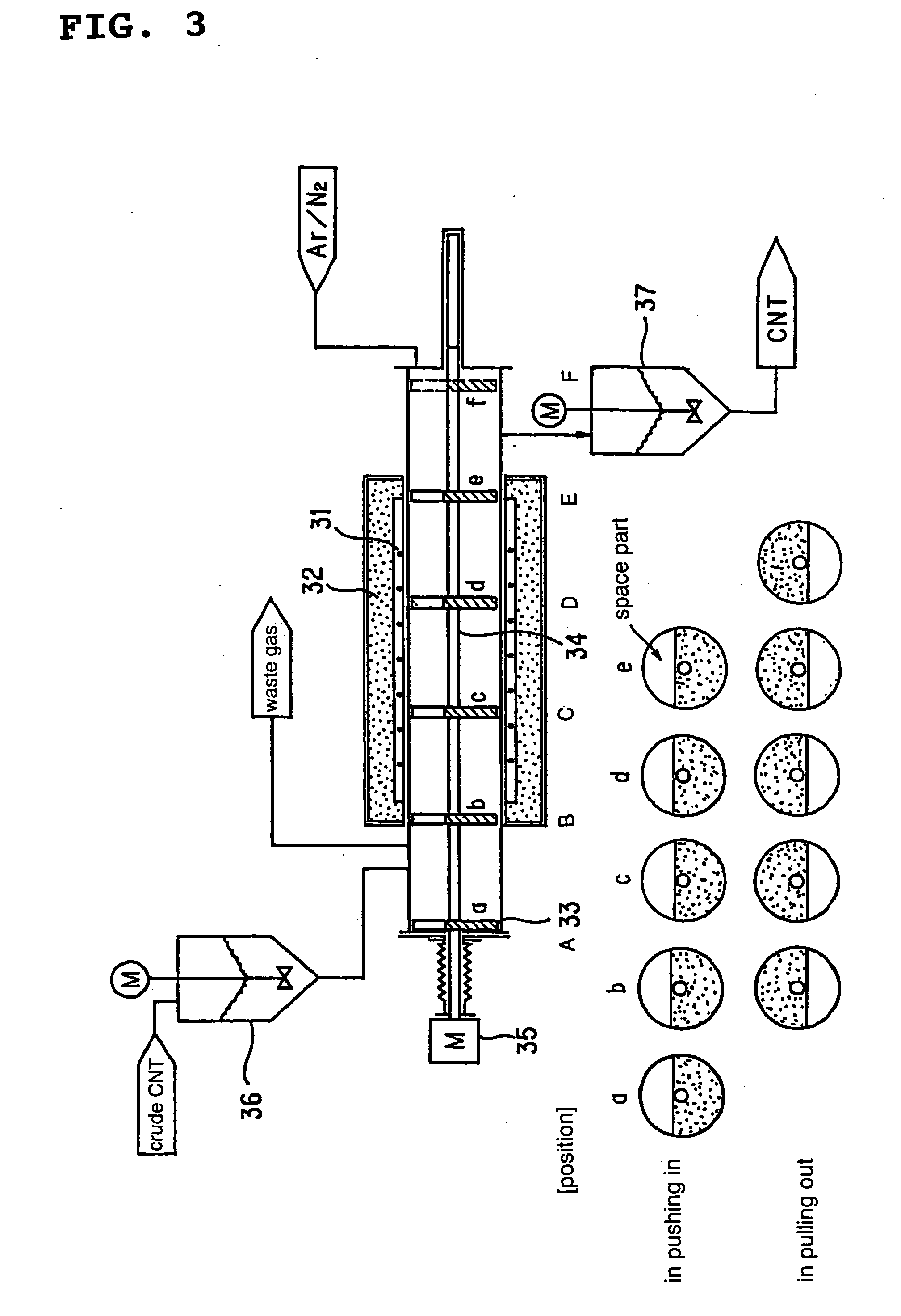
[0083] Carried out using equipment shown in FIG. 3.

[0084] It is a lateral batchwise heating furnace having an inner diameter of 200 mm, and push-in plates (33) are mounted on a movable shaft (34) disposed in a longitudinal direction of the furnace. This push-in plate has a notch part in a radius direction and assumes a structure in which it does not completely shut up a conduit. In the present example, a structure in which a segment of a circle is cut out has been assumed as shown in FIG. 3. The number of the push-in plates may be set up according to a push-in distance, and five plates of (a), (b), (c), (d) and (e) have been set in the present example. Further, the push-in plates are fixed on the movable shaft, and the fixing directions are set up so that the notch parts of the respective plates are overlapped when observing them along the shaft. The above movable shaft is prepared from a graphite material. The positions of the respective pu...


PUM


Abstract

Provided are a powder heat treatment process, wherein fine carbon fibers are heated in a heating furnace at a temperature of 800° C. or higher under an inert gas atmosphere or a hydrogen gas atmosphere in the form of powder taken out from a reaction furnace for producing the fine carbon fibers or after compressing and crushing the fine carbon fibers to turn them into amorphous powder without filling them into a specific vessel or compaction-molding them to thereby vaporize volatile components stuck to the fibers and carbonize them at a higher temperature and powder heat treatment equipment, wherein a heating furnace part is partitioned by push-in plates for fine carbon fibers or stirring devices in the furnace; a surrounding gas-discharging port is provided in a part close to a fiber-charging port out of compartments partitioned by the above plates or devices; and a gas-feeding port is provided in a part close to an outlet for the above fibers.

Description

TECHNICAL FIELD [0001] The present invention relates to a production process for a fine carbon fiber material which is excellent in characteristics such as electron emitting ability, hydrogen storage ability, electroconductivity and thermal conductivity and which is used for various secondary batteries including a Li ion battery, fuel cells, FED, superconductive devices, semiconductors and electroconductive composite materials and production equipment, more specifically to a heat treatment process for turning vapor grown carbon fibers produced by a CVD process under non-oxidative atmosphere, single-walled and multiwalled carbon nanotubes or mixtures of the above carbon nanotubes into products having a required quality and heat treatment equipment. BACKGROUND ART [0002] A lot of unreacted organic compounds and polymers are sometimes contained as volatile tarry matters in so-called as-grown products taken out from a reaction furnace in the case of vapor grown carbon fibers and carbon ...

Claims


Application Information

Patent Timeline
IPC IPC(8): C01B31/02F23C5/00D01F9/127D01F9/133
CPCB82Y30/00D01F9/133D01F9/127
Inventor NISHIMURA, KUNIO
Owner MITSUI & CO LTD
Why Eureka
Try Eureka