Polarizer for high-power deep UV radiation

Inactive Publication Date: 2006-03-09
CORNING INC
View PDF11 Cites 14 Cited by
  • Summary
  • Abstract
  • Description
  • Claims
  • Application Information

AI Technical Summary

Benefits of technology

[0015] Another embodiment of the invention as polarization-sensitive routing system for ultraviolet light has a working optical pathway for conveying an unpolarized beam of ultraviolet light having a wavelength less than 250 nm. An antireflector is inclined to the working optical pathway such that rays within the unpolarized beam of ultraviolet light encounter the antireflector at angles of incidence above Brewster's angle. The antireflector includes a plurality of layers that exploit a mechanism of interference for re

Problems solved by technology

Polarizing ultraviolet light at wavelengths below 250 nm, particularly at power densities above five milli-joules per centimeter squared per pulse, presents special challenges.
The typical optical materials for longer wavelength applications are either insufficiently transmissive or subject to breakdown at the short wavelengths and high power densities.
Thus, the challenges for conveying or manipulating such light at somewhat lower concentrations are high.
However, such polarizers cannot be used in the specified UV energy regime, because the UV radiation breaks down all of the known cements.
However, even such precisely mating surfaces have defects containing atmospheric materials that suffer slight surface absorption, which causes heating and subsequent delamination.
However, some distortion occurs at each of the reflective interface

Method used


Image

  • Polarizer for high-power deep UV radiation
  • Polarizer for high-power deep UV radiation
  • Polarizer for high-power deep UV radiation

Examples


Embodiment Construction

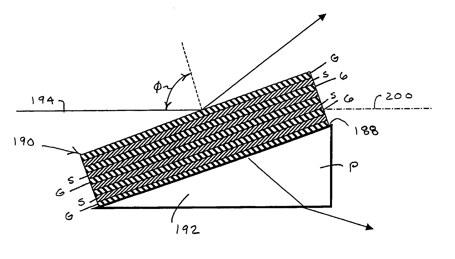
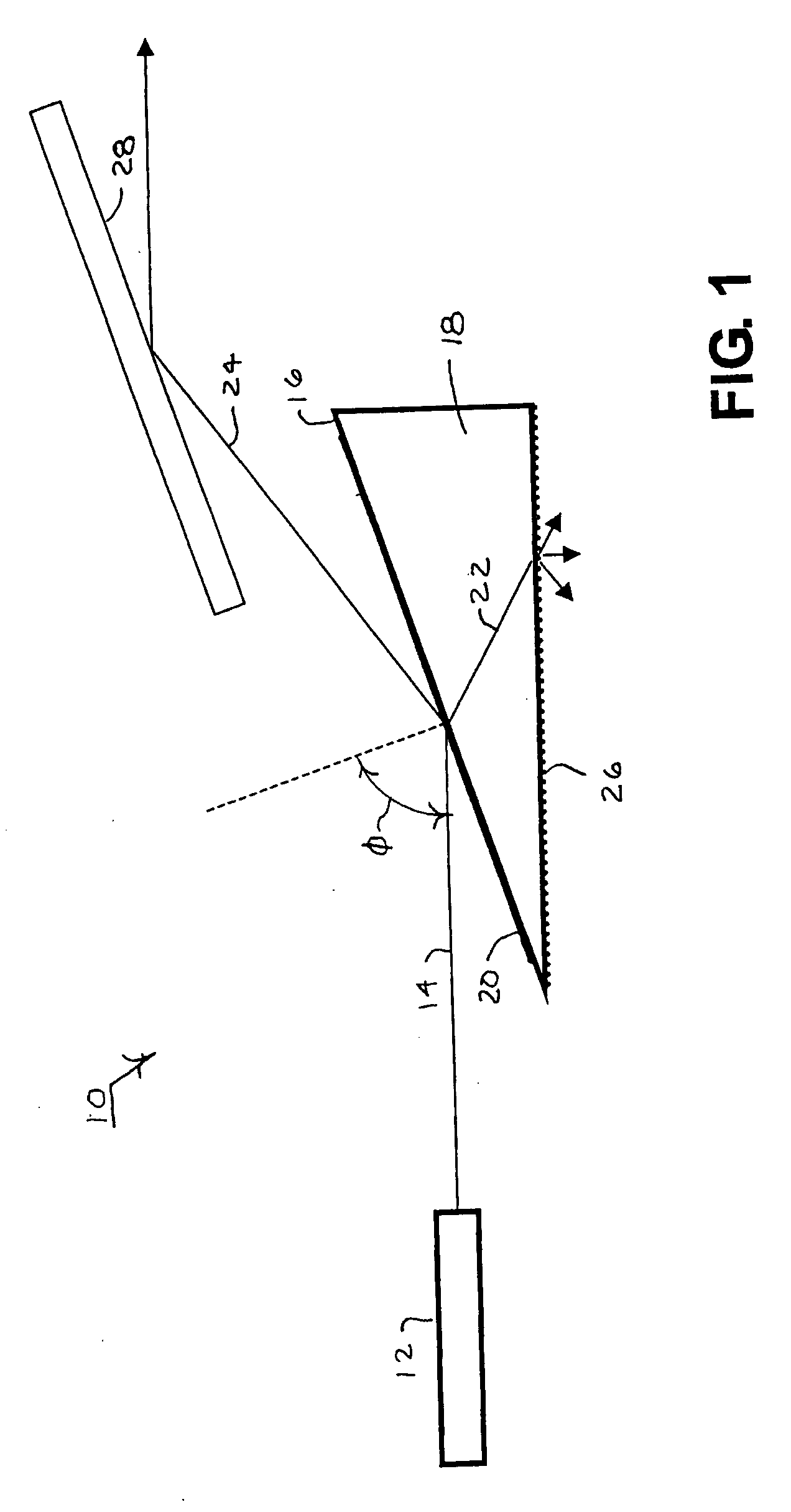
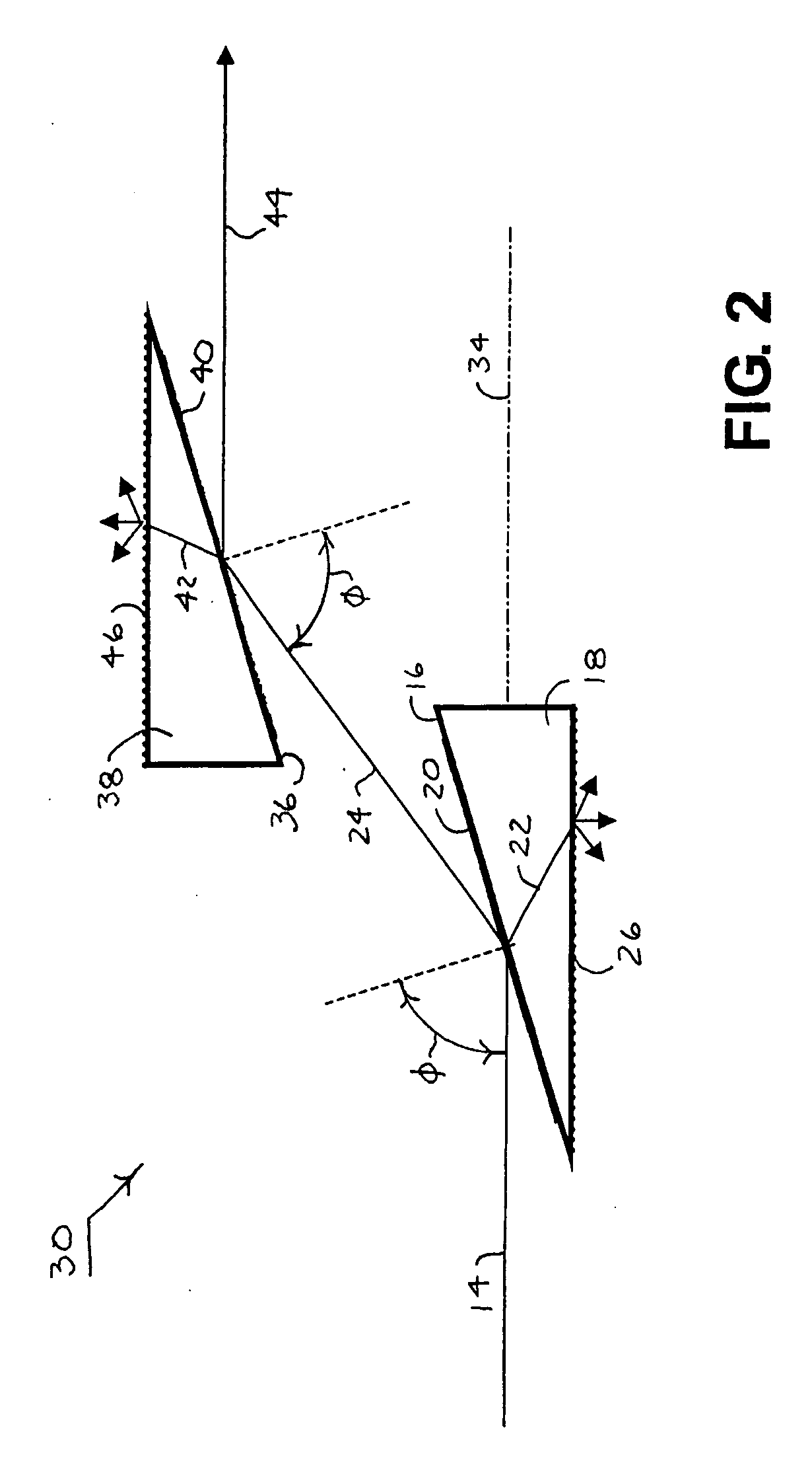
[0035] A polarizing system 10 is shown in FIG. 1 of the type that can be used for the practice of the present invention includes a laser light source 12, such as an excimer laser, that emits a collimated beam of unpolarized light 14 having a nominal wavelength less than 250 nm (e.g., 193 nm or 157 nm) and a power density greater than 5 milli-joules per square centimeter per pulse. Such an unpolarized beam 14 is not limited to randomly polarized light but also includes insufficiently or inappropriately polarized light. The collimated beam 14 approaches a leading surface 16 of a prism 18 at an incidence angle φ between 65° and 75°. As unpolarized light, the incident beam 14 includes both P polarization components that oscillate in the plane of incidence (i.e., the plane of FIG. 1) and S polarization components that oscillate normal to the plane of incidence.

[0036] An antireflective coating 20 is applied to the leading surface 16 of the prism 18 to differentially affect orthogonally r...


PUM


Abstract

A polarizing effect is achieved for light having wavelengths less than 250 nm by orienting an antireflector at an incidence angle between 65° and 75°. Despite limited choices for materials, the antireflector is constructed of layers that alternate in refractive index to exploit the mechanism of interference for limiting the reflectivity of one linear polarization component of the light. The same combination of layers supports the reflectivity of an orthogonal linear polarization component. The light reflected from the antireflector is highly polarized.

Description

FIELD OF THE INVENTION [0001] The invention relates to the polarization of light within the deep UV spectrum at wavelengths of less than 250 nm, particularly at high power densities above 5 milli-joules per square centimeter per pulse. DESCRIPTION OF RELATED ART [0002] Polarizing ultraviolet light at wavelengths below 250 nm, particularly at power densities above five milli-joules per centimeter squared per pulse, presents special challenges. The typical optical materials for longer wavelength applications are either insufficiently transmissive or subject to breakdown at the short wavelengths and high power densities. Excimer lasers operating at 157 nm can be arranged to cut through all known solids including diamonds. Thus, the challenges for conveying or manipulating such light at somewhat lower concentrations are high. [0003] Traditional polarizers are available in a number of different designs. These include cemented birefringent crystals in different relative orientations. The ...

Claims


Application Information

Patent Timeline
IPC IPC(8): G02F1/13
CPCG02B5/3075G02B5/3041
Inventor MAIER, ROBERT L.GOODMAN, DOUGLAS S.
Owner CORNING INC
Why Eureka
Try Eureka