Flaky carbonaceous particle and production method thereof

a carbonaceous particle and flaky technology, applied in the field of flaky carbonaceous particle production, can solve the problems of difficult methods to manufacture carbonaceous particle of high purity in large quantities at a low cost, and achieve excellent electron emission performance, excellent characteristics, and high electron conductivity

Inactive Publication Date: 2006-03-23
CANON KK
View PDF6 Cites 21 Cited by
  • Summary
  • Abstract
  • Description
  • Claims
  • Application Information

AI Technical Summary

Benefits of technology

[0008] It is an object of the present invention to provide a carbonaceous particle which has an excellent field electron emission performance, has a high electron conductivity, particularly shows excellent characteristics when used for secondary batteries, and can be suitably applied to various devices other than secondary batteries, as well.
[0009] It is another object of the invention to provide a method for inexpensively mass-producing the carbonaceous particles.
[0021] The hexagonal, flaky carbonaceous particle having the particular appearance / shape and internal structure, which is provided by the present invention and is described above, can be said to be a novel carbonaceous particle, because it can objectively be distinguished and is different from conventional carbonaceous particles. The carbonaceous particle provided by the present invention is useful in industries, because of having an excellent electron emission performance and a high electron conductivity, due to having the above-mentioned fine structure, and shows excellent characteristics particularly when used for a secondary battery. In addition, the carbonaceous particle can inexpensively be provided to a market, because of employing a carbon-containing compound, which is comparatively inexpensive and easily available, as a raw material, and can be effectively manufactured by a comparatively easy production method as mentioned above.

Problems solved by technology

However, the above-mentioned prior art methods of producing a carbonaceous particle such as a fullerene and a carbon nanotube, provide carbonaceous particles of a low purity, have problems in a production apparatus and a purification process, and consequently it is difficult for the methods to manufacture carbonaceous particles of a high purity in large quantities at a low cost.

Method used


Image

  • Flaky carbonaceous particle and production method thereof
  • Flaky carbonaceous particle and production method thereof
  • Flaky carbonaceous particle and production method thereof

Examples


example 1

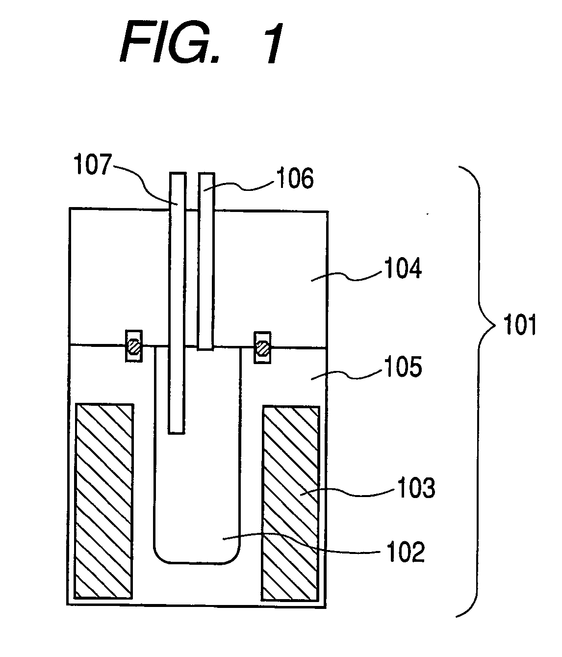
[0075] In the present example, carbonaceous particles (Sample No. S-01) were produced under the production conditions shown in Table 1 with the use of the production apparatus shown in FIG. 1 and raw materials shown in the table.

[0076] The production procedure includes firstly introducing the raw materials shown in Table 1 into the reaction vessel 102 of the production apparatus shown in FIG. 1, sealing the reactor with the upper sealing member 104, then heating the inside of the reaction vessel 102 to 450° C. with a heater 103, and keeping the inside of the reaction vessel 102 at this temperature through a temperature-detecting means 107 while keeping the pressure inside the reaction vessel 102 at a predetermined pressure with the pressure controller 106. While keeping this condition, the raw materials in the reaction vessel 102 were reacted with each other for 12. At that time, the ultimate pressure in the reaction vessel was 28 MPa. After completing the reaction, the reaction ve...

example 2

[0078] The field electron emission characteristics of the carbonaceous particle obtained in Example 1 were evaluated by using the field electron emission device shown in FIG. 5. At first, the carbonaceous particle of 0.22 g, which was obtained in Example 1 and ground with a planetary ball mill, was added to 75 ml of isopropyl alcohol, and was subjected to ultrasonic waves for six hours to obtain a homogeneous dispersion liquid. Then, electrodeposition was performed by application of a DC voltage of 100 V for five minutes, while being stirred with a magnet stirrer. Both anode and cathode used in the electrodeposition were stainless steel substrates. The electrodeposited substrate (electrode; 503a / 505) was mounted on the glass substrate 502a of the measuring device 501 in FIG. 5; then the mica plate 504, the opposing electrode (stainless steel) 503b and the glass plate 502b were stacked in the named order to make a measurement cell, which was put in the measuring device 501; and a vol...

example 3

[0082] The carbonaceous particles obtained in Example 1 were calcined in an inert gas at 2,500° C. to remove metallic component therefrom. The thus calcined carbonaceous particles were mixed with a binder and an alcohol to make a paste, and the paste was applied to a current collector made of a copper foil to prepare a negative electrode. Separately, a positive electrode was prepared by using lithium cobalt oxide. By using the negative electrode and the positive electrode, a lithium secondary battery having the configuration shown in FIG. 7 was made according to the above-described lithium secondary battery production method. As a result of evaluating the charge / discharge efficiency of the thus obtained lithium secondary battery thorough a charge / discharge cycle test, the charge / discharge efficiency at the 50th cycle was as good as 1.12, when that of a lithium second battery using graphite for a negative electrode was defined as 1.0.

[0083] Generally, at the time of electrode format...


PUM

PropertyMeasurementUnit
thicknessaaaaaaaaaa
side lengthaaaaaaaaaa
crystal lattice spacingaaaaaaaaaa

Abstract

A carbonaceous particle is provided which comprises a hexagonal flake formed of an aggregate of a plurality of nanocarbons and having a side length of 0.1 to 100 mm and a thickness of 10 nm to 1 mm. Thereby, a carbonaceous particle is provided which has an excellent electron emission performance, has a high electron conductivity, shows excellent characteristics particularly when used for a secondary battery, and can suitably be applied to various devices other than a secondary battery as well.

Description

TECHNICAL FIELD [0001] The present invention relates to a carbonaceous particle having an excellent electron emission performance and a high electron conductivity, and a production method therefor. BACKGROUND ART [0002] Since fullerene (Buckminster fullerene C60), a soccer ball shaped molecule consisting of 60 carbon atoms, was discovered by H. W. Kroto, R. E. Smallry, and R. F. Curl in 1985, and a carbon nanotube, a tube formed of a rolled graphene sheet (a hexagonal carbon network plane) was discovered by Iijima in 1991, methods of producing the so-called carbonaceous particles including fullerene and carbon nanotubes, have been developed, and applications of the carbonaceous particles to various fields are being investigated. [0003] Methods proposed of producing a fullerene include: the oven laser-vaporization method for extracting a fullerene from soot obtained by irradiating graphite with a laser in an argon gas flow heated to a high temperature of about 1,200° C.; the resistiv...

Claims


Application Information

Patent Timeline
Patent Type & Authority Applications(United States)
IPC IPC(8): C01B31/02B82B1/00B82B3/00B82Y30/00B82Y40/00B82Y99/00H01J1/304H01J9/02H01M4/587H01M10/05
CPCB82Y30/00B82Y40/00C01B31/02C01B31/0206H01M4/587Y10S977/758H01M2004/021Y10S977/755Y10S977/734Y10S977/775Y10S977/832H01M10/0525C01B32/05C01B32/15Y02E60/10
Inventor SANO, HITOMIKAWAKAMI, SOICHIROYAMAMOTO, TOMOYAINOUE, KATSUHIKO
Owner CANON KK
Why Eureka
Try Eureka