
Carbon nanoballoon structure and method for preparation thereof, and electron emitter

a carbon nanoballoon and balloon body technology, applied in the direction of discharge tube/lamp details, energy-based chemical/physical/physical-chemical processes, nanoinformatics, etc., can solve the problems of inability to efficiently and stably obtain a nanometer-sized hollow carbon structure having a large inner space, and the method of efficiently and stably obtaining such a structure has not yet been put into practice, so as to achieve easy and stably production of such a

Inactive Publication Date: 2010-07-13
TAKIKAWA HIROFUMI +2
View PDF9 Cites 0 Cited by
  • Summary
  • Abstract
  • Description
  • Claims
  • Application Information

AI Technical Summary

Benefits of technology

The present invention provides a hollow carbon nanoballoon structure with a large closed space and a method of producing it. The carbon nanoballoon structure has excellent electrical conductivity, lubricity, heat resistance, chemical stability, and chemical resistance. It also has low bulk density and excellent insulating properties. The carbon nanoballoon structure can be easily and stably produced using arc discharge or laser irradiation. It can be used as an electron emitter with excellent electron emission properties.

Problems solved by technology

Since the carbon polyhedron does not necessarily have a hollow inner space and has a relatively small particle diameter ranging from several to several tens of nanometers, a number of substances cannot be provided in the carbon polyhedron.
Specifically, a method of efficiently and stably obtaining a nanometer-sized hollow carbon structure having a large inner space has not yet been put into practice.

Method used


Image

  • Carbon nanoballoon structure and method for preparation thereof, and electron emitter
  • Carbon nanoballoon structure and method for preparation thereof, and electron emitter
  • Carbon nanoballoon structure and method for preparation thereof, and electron emitter

Examples


example 1

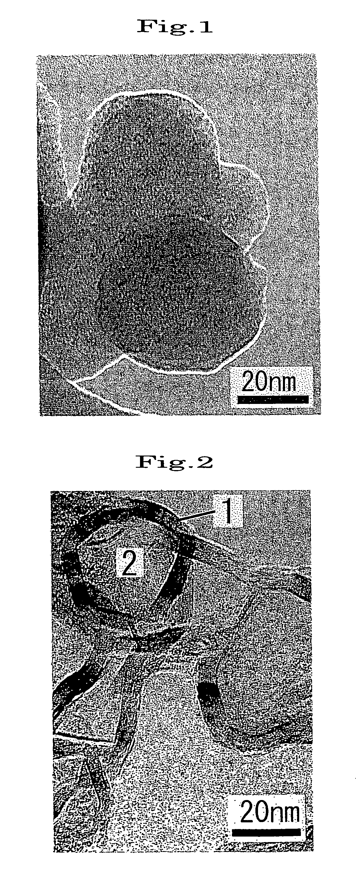
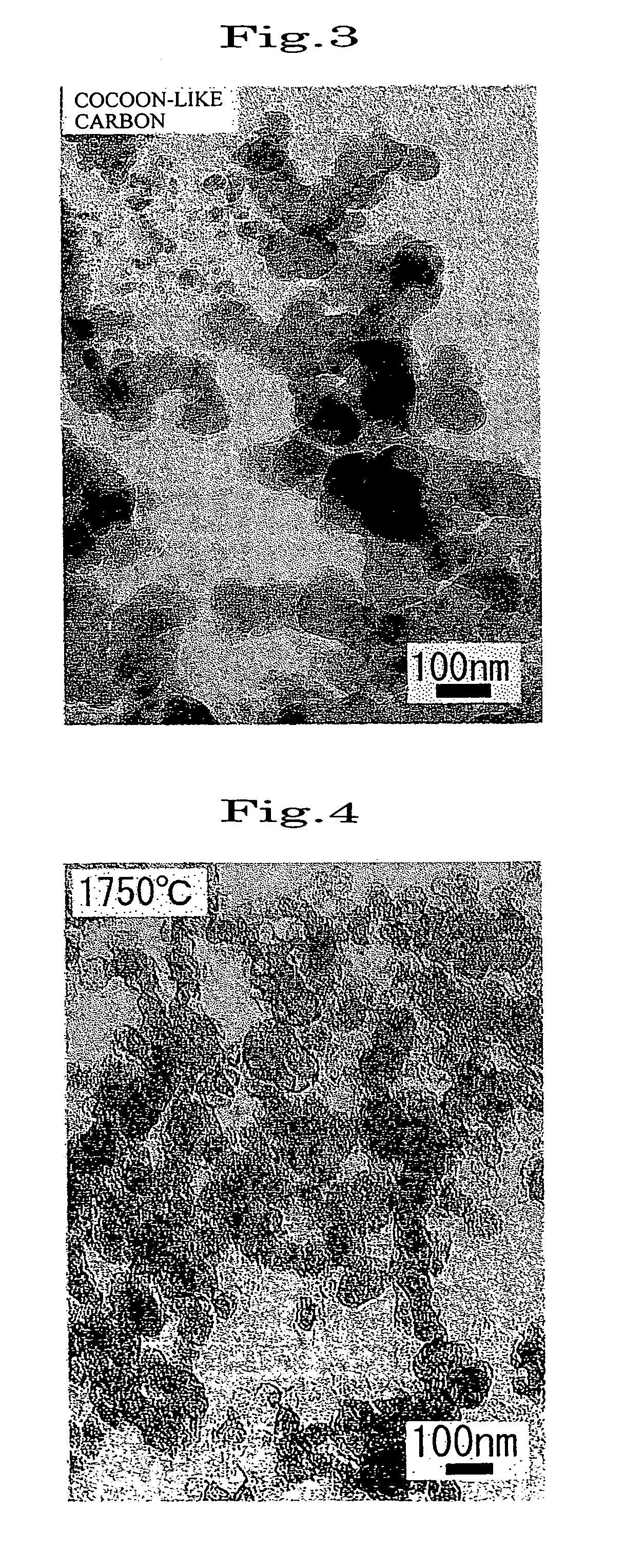
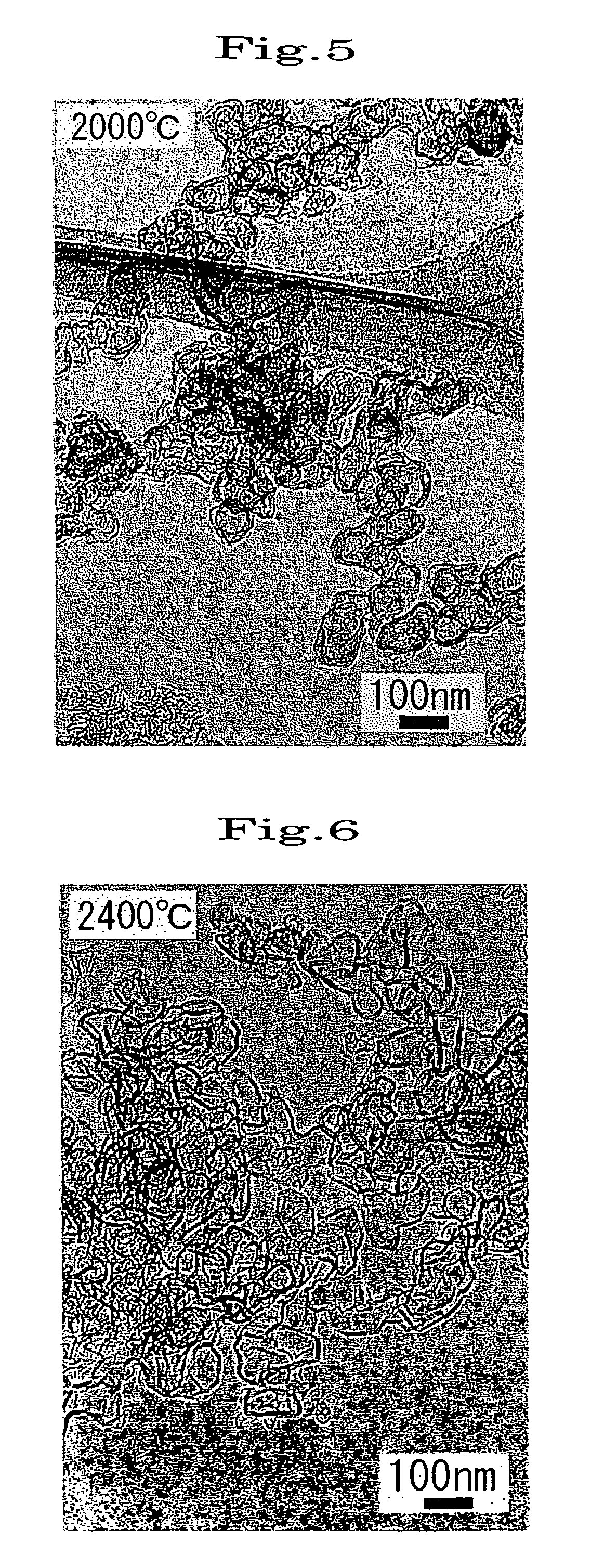
[0053]Soot prepared by arc discharge using two graphite electrodes in a nitrogen atmosphere was heated at 2800° C. for one hour in an argon gas atmosphere using a Tammann furnace. The resulting soot was observed using a transmission electron microscope (TEM). It was confirmed that hollow structures were formed in which graphite sheets were linked to form a curved surface and which entirely or partially had various shapes such as a sphere, a gourd-like shape, or a triangular pyramidal shape. About 70% or more of the particles had a number of graphite sheets of 10 to 16, a diameter of the structure of 30 to 100 nm, and a void content of the hollow portion of 45 to 80%. The maximum major axis was 500 nm, and the minimum minor axis was 20 nm. A structure in which two or more particles were bonded was also observed. The DBP absorption indicating the degree of structure was about 100 ml / 100 g.

[0054]A similar carbon nanoballoon structure was also obtained when heating soot, prepared by an ...

example 2

[0055]Commercially available Ketjenblack (Ketjenblack EC-600JD produced by Ketjenblack International Corporation) was heated at 2800° C. for one hour in an argon gas atmosphere using a Tammann furnace. The resulting soot was observed using a TEM. About 70% or more of the particles were carbon nanoballoon structures with a number of graphite sheets of 8 to 14, a diameter of 30 to 50 nm, and a void content of 40 to 75%.

example 3

[0056]The carbon nanoballoon structure obtained in Example 1 was oxidized in air at 600° C. for one hour. The specific surface area of the resulting carbon nanoballoon structure doubled to 70 m2 / g from 35 m2 / g before oxidation. This indicates that an opening reaching the hollow portion was formed in the structure. The oxidized structure was observed using a TEM. The opening had a diameter of 5 to 20 nm.


PUM

PropertyMeasurementUnit
temperatureaaaaaaaaaa
particle diameteraaaaaaaaaa
specific surface areaaaaaaaaaaa

Abstract

A hollow carbon nanoballoon structure having a relatively large closed space, and a method of producing a carbon nanoballoon structure capable of easily and stably producing such a structure. The carbon nanoballoon structure is obtained by heating soot prepared by an arc discharge using carbon electrodes, soot prepared by vaporizing carbon by laser irradiation, or carbon black having a specific surface area of 1000 m2 / g or more and a primary particle diameter of 20 nm or more at a high temperature in an inert gas atmosphere, and includes graphite sheets linked to form a curved surface.

Description

TECHNICAL FIELD[0001]The present invention relates to a hollow carbon nanoballoon structure, a method of producing the same, and an electron emitter.BACKGROUND ART[0002]A carbon material (fullerene soot) having a nanometer-sized microstructure is contained in soot prepared by vaporizing carbon by arc discharge using graphite electrodes or laser irradiation to carbon in an inert atmosphere, and allowing the vaporized carbon to aggregate through gradual cooling. As the configuration of fullerene soot, a single-wall sphere represented by C60, a multiwall sphere having a small void formed therein (carbon nanoparticle), a single-wall tube contained in soot prepared by vaporizing carbon by an arc discharge using graphite in which a specific metal catalyst is mixed (single-wall carbon nanotube), and a multiwall tube in which several single-wall nanotubes are concentrically arranged (multiwall carbon nanotube: deposited on the surface of the cathode when using graphite in which a metal cata...

Claims


Application Information

Patent Timeline
Patent Type & Authority Patents(United States)
IPC IPC(8): B01J19/08B82B1/00C01B31/02H01J1/304
CPCB82Y10/00B82Y30/00C01B31/0233H01J1/304B82Y40/00H01J2201/30469C01B32/162
Inventor TAKIKAWA, HIROFUMIKONDO, AKIRAYOSHIKAWA, KAZUOITOH, SHIGEO
Owner TAKIKAWA HIROFUMI
Learn More