Variable charge films for controlling microfluidic flow

a microfluidic flow and charge film technology, applied in the field of microfluidics, to achieve the effect of improving separation efficiency

Active Publication Date: 2006-03-30
FLORIDA STATE UNIV RES FOUND INC
View PDF32 Cites 27 Cited by
  • Summary
  • Abstract
  • Description
  • Claims
  • Application Information

AI Technical Summary

Benefits of technology

[0014] Among the aspects of the present invention may be noted the provision of pH sensitive PEMU films for coating the interior surfaces of microfluidic channels, such that the direction and magnitude of electroosmotic flow of aqueous compositions through the microfluidic

Problems solved by technology

However, proteins are remarkably tenacious adsorbers, du

Method used


Image

  • Variable charge films for controlling microfluidic flow
  • Variable charge films for controlling microfluidic flow
  • Variable charge films for controlling microfluidic flow

Examples


example 1

Quantitative and Qualitative Techniques for Use in Characterizing PEMUs

[0088] The following techniques were used to characterize the PEMUs of the present invention. Transmission IR spectra were recorded with a Nicolet Avatar 360 FTIR spectrometer. The thickness of the dried multilayers was measured with a Gaertner Scientific L116S ellipsometer, using 632.8 nm light at 70° incidence angle. A refractive index of 1.55 was employed for multilayers. Atomic force microcopy, AFM (Dimension 3100, Digital Instruments) in Tapping Mode™ was used to track the multilayer surface morphology change.

[0089] ATR measurements were performed with a Nicolet Nexus 470 fitted with a 0.5 mL capacity flow-through ATR assembly (Specac Benchmark) using a 70×10×6 mm 45° germanium crystal. Each spectrum had 32 scans coadded at a resolution of 4 cm−1. Multilayers were deposited on the ATR crystal while it was loaded in the flow cell by passing polyelectrolyte and rinse solutions, in an alternating manner, thro...

example 2

Characterizing a PEMU System Comprising a Blend of Copolymer and Homopolymer as the Polycation

[0090] A PEMU comprising a blend of two polyelectrolytes as the polycation was deposited on a silicon wafer and characterized. This blend was used as a coating on the interior surface of a capillary. See EXAMPLE 4. A random copolymer PDADMA-co-PAA (Calgon Merquat® 281, mol % of AA is 36%; MW˜200,000) was used as one polycation component. Homopolymer PDADMA (Aldrich, MW=300,000-400,000) was also used as a polycation component. Polystyrene sulfonic acid, PSS, (Scientific Polymer Products, molecular weight, MW˜70,000) was used as the polyanion.

[0091] Silicon wafers (Si, 0.5 mm thick, 1 in. diameter, undoped, double-side polished from Topsil Inc.) were cleaned in “piranha” solution (70% H2SO4 (conc.) / 30% H2O(aq)) and then in H2O2 / ammonia / water 1:1:7 vol / vol, rinsed in distilled water and dried with a stream of N2.

[0092] To prepare multilayers on these Si wafers they were affixed to a stainle...

example 3

Stability of PEMUs to pH Shock

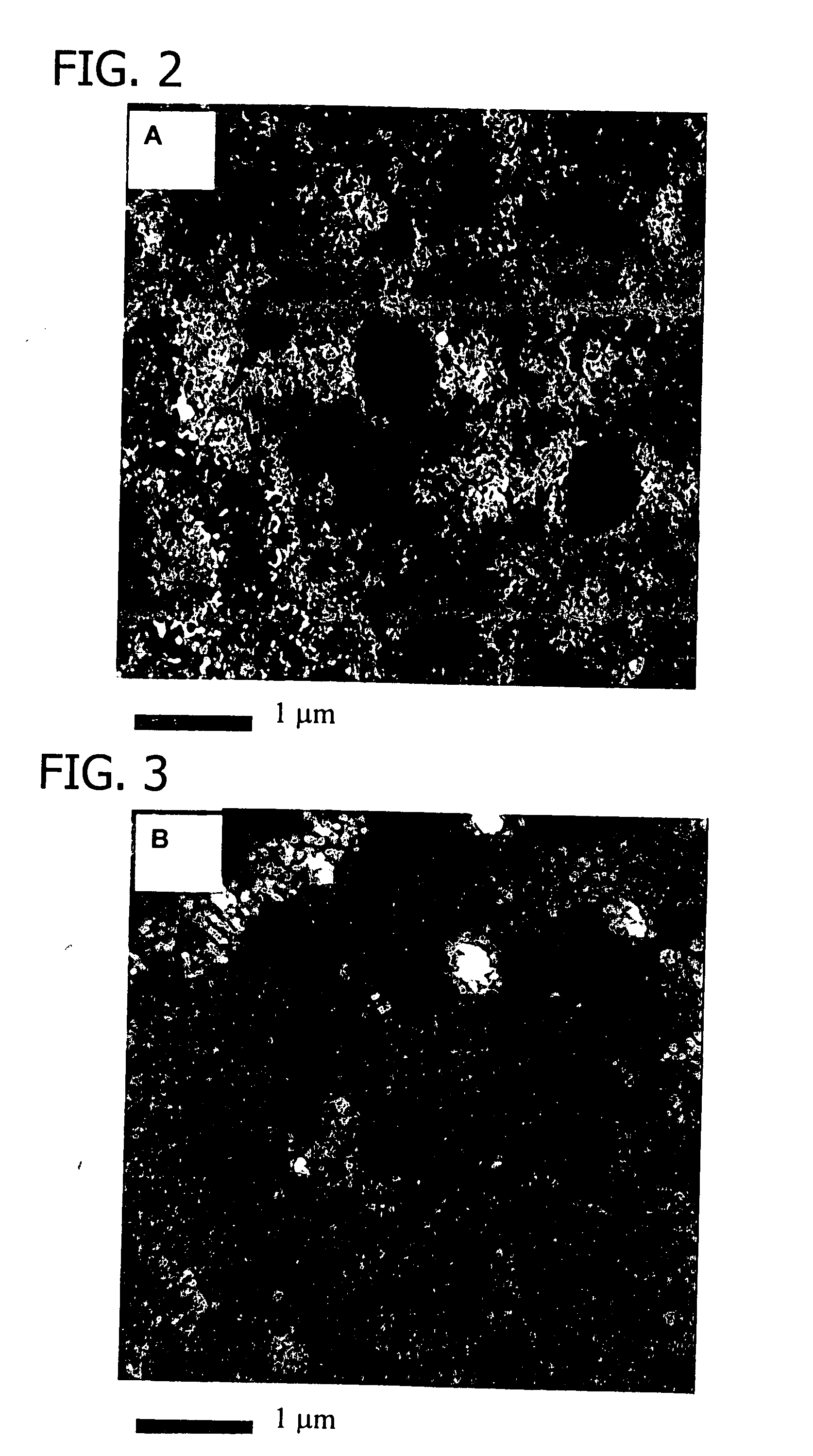
[0097] A key variable in pH-sensitive coatings was the total thickness of the PEMU. While it is desirable to minimize the number of layers deposited, a minimum number of layers are also required to mask the bare silica in a capillary. Microscopic investigations (Atomic Force Microscope) of 21-layer PEMUs on Si wafer revealed some evidence of pH-induced cratering in the surface, as seen in the micrograph in FIG. 2. PEMUs made with 11 layers showed no such topological nonidealities, as shown in the micrograph in FIG. 3. This difference was attributed to the loss of material from the surface of 21-layer PEMUs. Loss of thickness from multilayers on silicon wafers is evidence for not only polymer charge extrusion but also charge expulsion.

[0098] Multilayers were more stable as the content of pH-ionizable material decreased, and less stable when the last layer was negative as-deposited (PSS). To assess the stability of various combinations of PEMU, they wer...


PUM

PropertyMeasurementUnit
Fractionaaaaaaaaaa
Fractionaaaaaaaaaa
Fractionaaaaaaaaaa

Abstract

A microfluidic device for carrying a liquid, the device comprising a microfluidic channel having an interior wall and a polyelectrolyte film on the interior wall whereby liquid carried by the channel contacts the polyelectrolyte film, the polyelectrolyte film having a thickness of about 1 to about 1000 nanometers and comprising an interpenetrating network of a predominantly positively charged polymer and a predominantly negatively charged polymer, the predominantly positively charged polymer, the predominantly negatively charged polymer or both containing (i) a pH insensitive positively or negatively charged repeat unit having a pKa greater than 9 or less than 3, and (ii) a pH sensitive repeat unit, the pH sensitive repeat unit having a pKa of 3 to 9, whereby the pH of liquid in the microfluidic channel may be used to control the velocity or direction of electroosmotic flow of the liquid within said microfluidic channel.

Description

CROSS-REFERENCE TO RELATED APPLICATIONS [0001] This application claims priority from U.S. provisional application Ser. No. 60 / 549,341, filed on Mar. 2, 2004.STATEMENT REGARDING FEDERALLY SPONSORED RESEARCH [0002] This invention was made with Government support under Grant DMR 9727717 awarded by the National Science Foundation. The Government has certain rights in this invention.BACKGROUND OF THE INVENTION [0003] The present invention relates to the field of microfluidics and, more particularly, to using polyelectrolyte complex films to control the magnitude and direction of electroosmotic fluid flow within microfluidic channels. [0004] In the field of microfluidics, liquid is moved through passages of micrometers dimension. These passages may be isolated or interconnected, and may be part of a larger scheme for performing fluid manipulation for the purposes of analysis or synthesis, for example, in a lab-on-a-chip apparatus. Microfluidic flow may be employed for analytical separatio...

Claims


Application Information

Patent Timeline
IPC IPC(8): C07K1/26G01N27/447
CPCG01N27/44752
Inventor SCHLENOFF, JOSEPH B.SUI, ZHIJIE
Owner FLORIDA STATE UNIV RES FOUND INC
Why Eureka
Try Eureka