
Method and system for contamination detection and monitoring a lithographic exposure tool and operating method for the same under controlled atmospheric conditions

a technology of lithographic exposure and monitoring method, which is applied in the field of photolithographic formation of semiconductors, can solve the problems of affecting the uniformity of the wafer surface, the uncertainty of overlaying the image of the pattern for the current material layer, and the variation of the etched features

Inactive Publication Date: 2006-03-30
ADVANCED MICRO DEVICES INC +1
View PDF6 Cites 48 Cited by
  • Summary
  • Abstract
  • Description
  • Claims
  • Application Information

AI Technical Summary

Benefits of technology

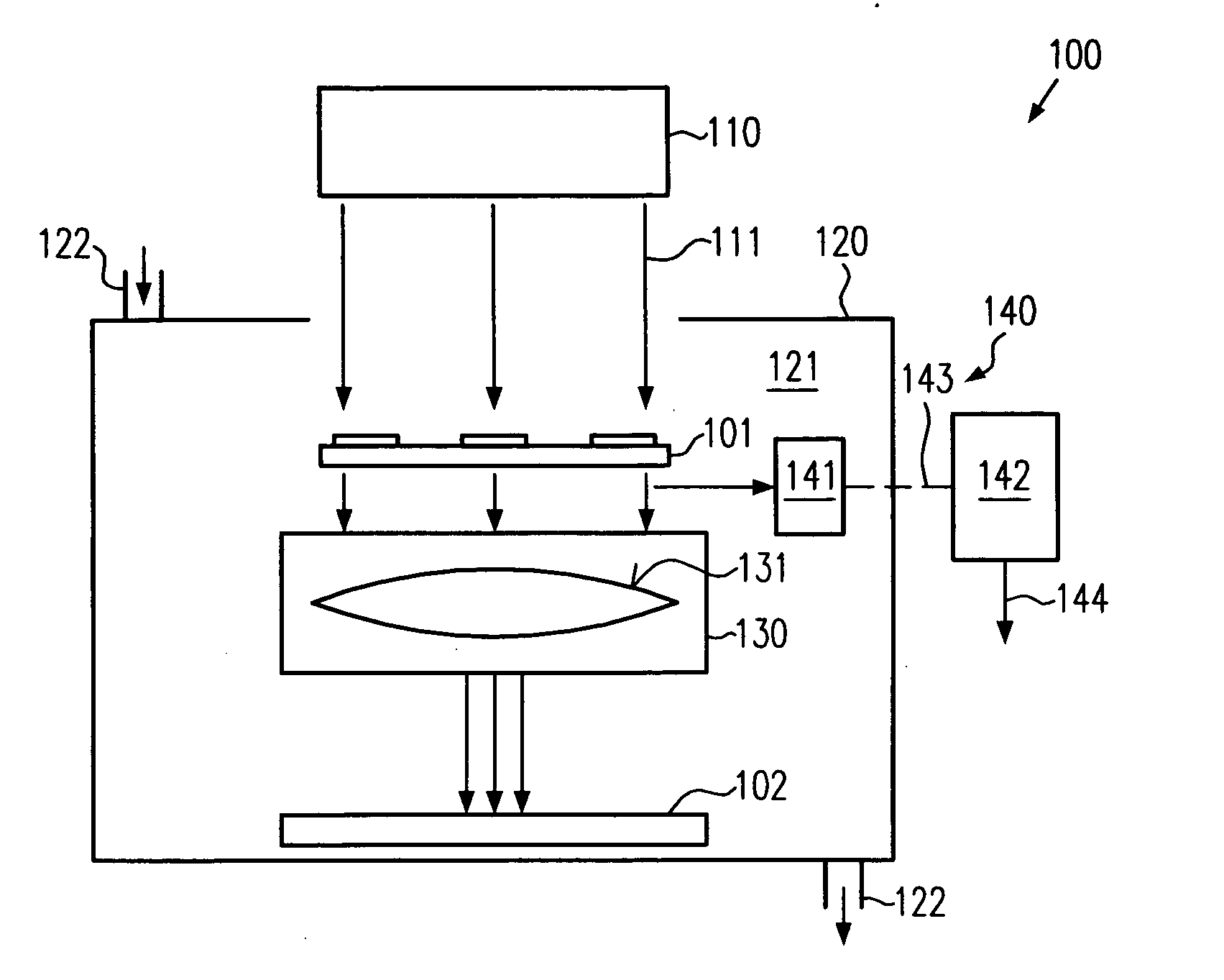
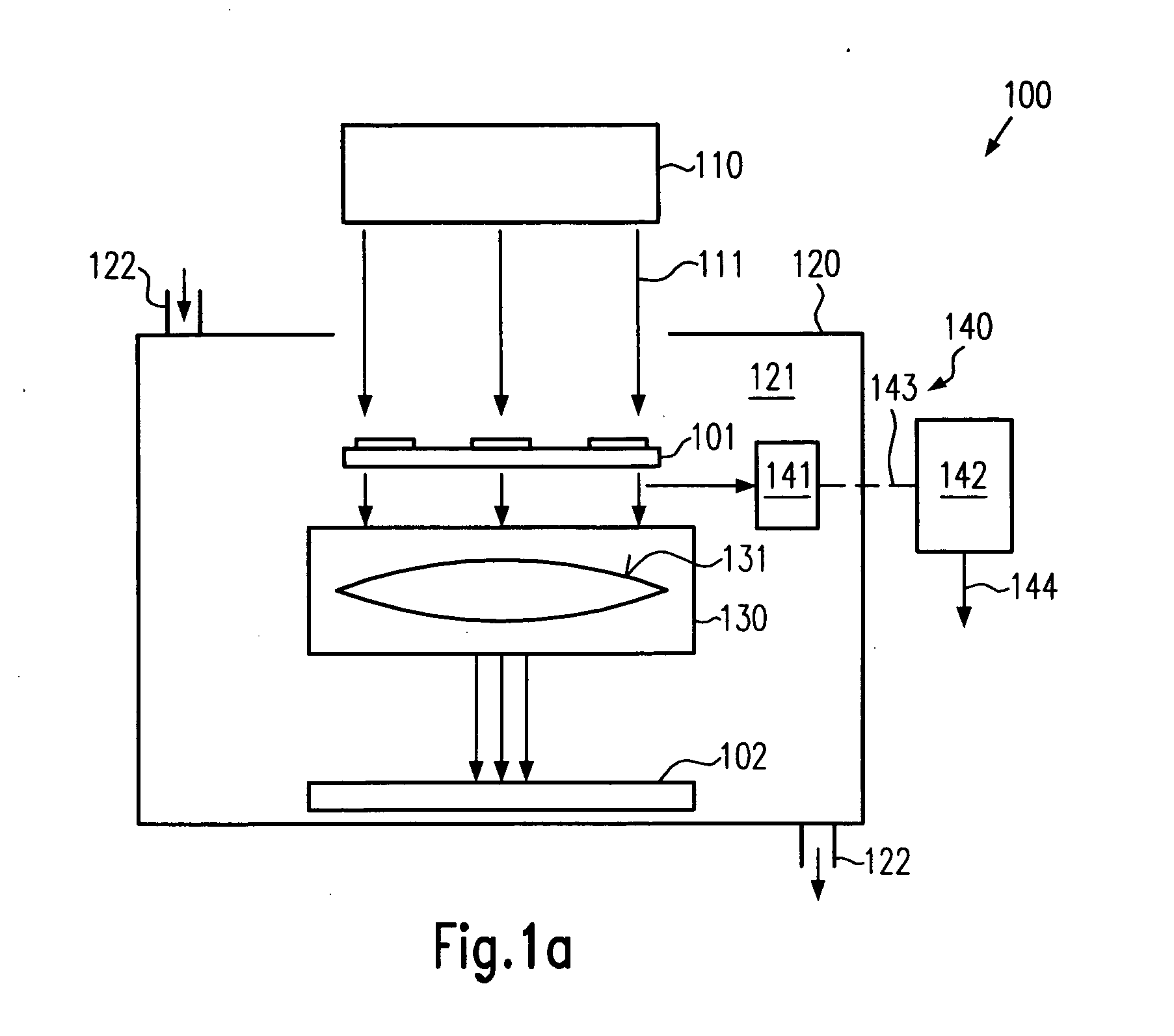
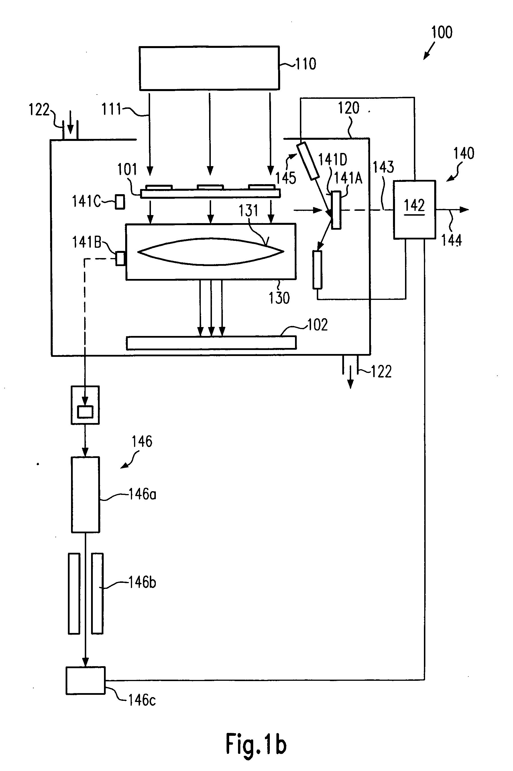
[0013] Generally, the present invention is directed to a system and a method for imaging features onto a substrate surface by lithography, especially by short wavelength lithography, in that the environmental conditions, that is, the surrounding atmosphere, of the optical elements and the substrate are taken into consideration during the lithographic process. Trace contaminations in the form of water, oxygen, carbon monoxide, carbon dioxide, volatile and condensable organic compounds, inorganic acidic gases, such as sulphur dioxide and nitrogen oxides, as well as silicon oxide compounds, such as silicones and siloxanes, may not only attenuate the exposure radiation but may also interact with the exposure radiation to form stable contamination layers on optical surfaces. According to the present invention, by taking into consideration the presence of any contamination and assessing the same as one further “tool parameter” to be accounted and monitored for during operation of an exposure tool, the adverse effects of contamination layers deposited on reticles, optical elements and the like, as well as the effects of light absorption and scattering by volatile molecular contaminants may be reduced.

Problems solved by technology

These registration tolerances are caused by, for example, a variation of a photoresist image on the substrate due to non-uniformities in such parameters as resist thickness, baking temperature, exposure and development.
Furthermore, non-uniformities of the etching processes can also lead to variations of the etched features.
In addition, there exists an uncertainty in overlaying the image of the pattern for the current material layer to the pattern of the previously formed material layer while photolithographically transferring the image onto the substrate.
Large diameters, although desirable in view of economical considerations, may, however, exacerbate the problem of non-uniformities across the wafer surface, especially as the minimum device dimensions, also referred to as critical dimensions (CD), steadily decrease.
Otherwise, the fluctuations across the wafer (and the wafer-to-wafer variations) may have to be taken account of, thereby requiring a circuit design that tolerates higher process discrepancies, which usually results in reduced device performance.
Especially, the inorganic salts cause haze effects, which are referred to as progressive defects, since the defect rate increases over the course of production usage of reticle and lens elements, even if the reticles have been determined to be clean prior to the usage for semiconductor production.
Although investigations have shown that these progressive defects may be observable at almost all lithographic wavelengths, this contamination problem is especially severe in the 193 nm lithography, particularly in combination with the processing of 300 mm wafers, which may become the standard substrate size of modern integrated circuit facilities.
The contaminations of optical surfaces are typically inhomogeneous in their composition and may usually exhibit a difference in refractive index compared to the optical elements, thereby causing light scattering and thus resulting in non-uniformities of the radiation flux incident on the wafer plane.
Moreover, in extreme cases, the contamination may render the optical elements unusable after a certain period of operation at reduced reliability, which finally requires the replacement of these optical elements.
Moreover, the contamination may cause significant variation during the imaging of critical circuit elements, such as gate electrodes of field effect transistors, thereby significantly affecting production yield and device performance.

Method used


Image

  • Method and system for contamination detection and monitoring a lithographic exposure tool and operating method for the same under controlled atmospheric conditions
  • Method and system for contamination detection and monitoring a lithographic exposure tool and operating method for the same under controlled atmospheric conditions
  • Method and system for contamination detection and monitoring a lithographic exposure tool and operating method for the same under controlled atmospheric conditions

Examples


Embodiment Construction

[0021] Illustrative embodiments of the invention are described below. In the interest of clarity, not all features of an actual implementation are described in this specification. It will of course be appreciated that in the development of any such actual embodiment, numerous implementation-specific decisions must be made to achieve the developers' specific goals, such as compliance with system-related and business-related constraints, which will vary from one implementation to another. Moreover, it will be appreciated that such a development effort might be complex and time-consuming, but would nevertheless be a routine undertaking for those of ordinary skill in the art having the benefit of this disclosure.

[0022] The present invention will now be described with reference to the attached figures. Various structures, systems and devices are schematically depicted in the drawings for purposes of explanation only and so as to not obscure the present invention with details that are we...


PUM


Abstract

By using highly efficient detection techniques, such as chromatography and absorption spectroscopy, one or more contaminants may be identified and the concentration thereof may quantitatively be determined. In this way, the adverse effect on critical components of exposure tools, such as reticles and lenses in the form of, for instance, deposited inorganic salts, may significantly be reduced and the process performance may be enhanced.

Description

BACKGROUND OF THE INVENTION [0001] 1. Field of the Invention [0002] The present invention relates to the field of fabrication of integrated circuits, and, more particularly, to the photolithographic formation of semiconductor related features on a substrate. [0003] 2. Description of the Related Art [0004] Fabrication of integrated circuits requires the precise formation of features having dimensions as small as 50 nm and even less in sophisticated devices, wherein a very small tolerance for errors is required. Such features may be formed in a material layer formed above an appropriate substrate, such as a semiconductor substrate, a metal-coated substrate and the like. These features of precisely controlled size are generated by patterning the material layer by performing photolithography processes frequently in combination with etch processes. For instance, during the formation of circuit elements of an integrated circuit on and in a specific material layer, a masking layer may be f...

Claims


Application Information

Patent Timeline
Patent Type & Authority Applications(United States)
IPC IPC(8): G03B27/52
CPCG03F7/70925G03F7/70916
Inventor KNAPPE, UWEOKOROANYANWU, UZODINMA
Owner ADVANCED MICRO DEVICES INC
Learn More