Transmitter
a transmitter and transmitter technology, applied in the field of wireless transmitters, can solve the problems of power consumption, problem in practical use, and the inability of conventional class-a or class-ab high-frequency power amplifiers to achieve high efficiency, and achieve the effect of high efficiency operation
- Summary
- Abstract
- Description
- Claims
- Application Information
AI Technical Summary
Benefits of technology
Problems solved by technology
Method used
Image
Examples
embodiment 1
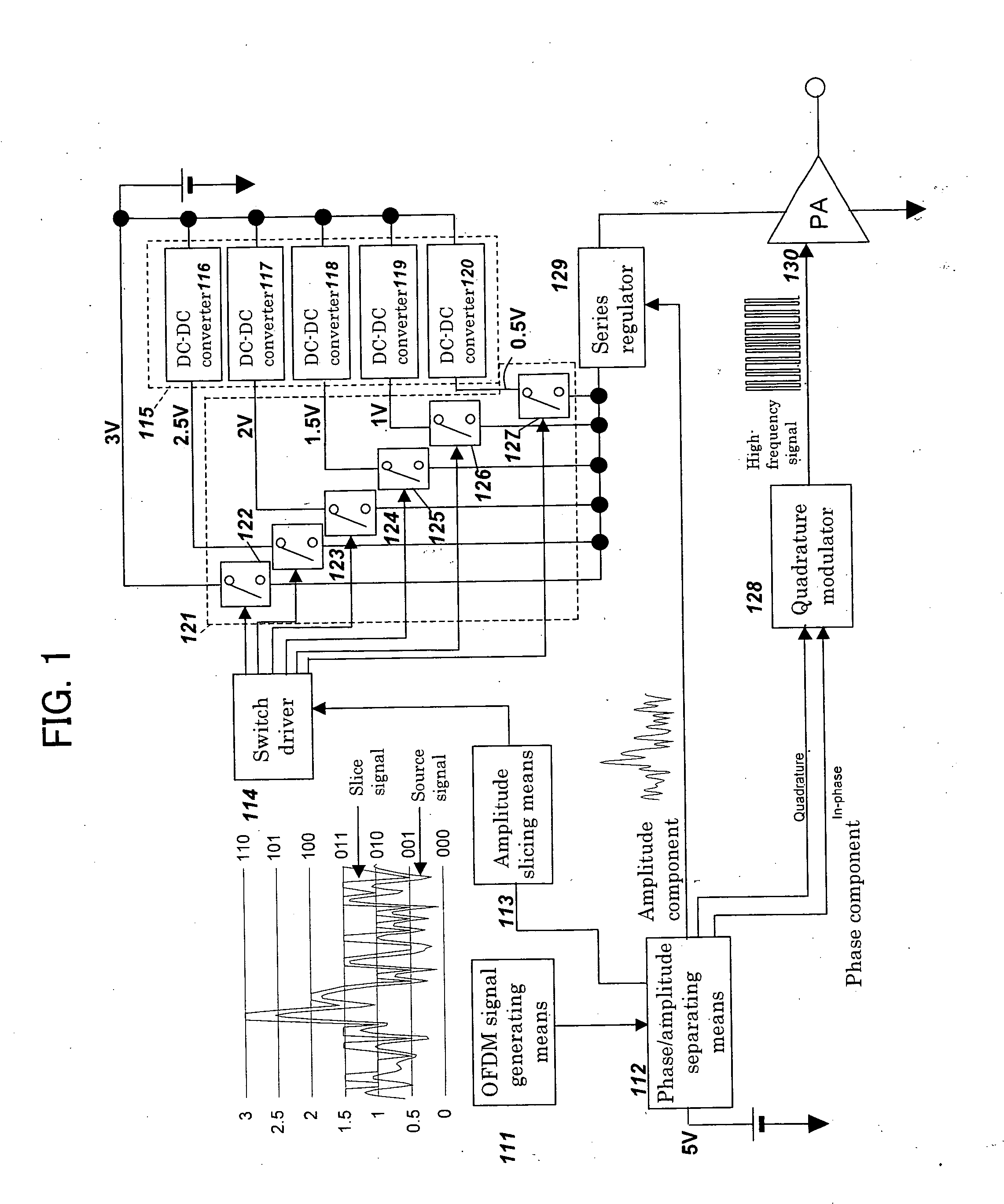
[0065] Embodiment 1 in accordance with the present invention will be described below referring to the drawing. In this embodiment, the wireless LAN system according to the IEEE802.11a Standard, wherein a wideband modulated signal is used, is taken as an example and explained. In the wireless LAN system, each of 52 quadrature subcarriers is subjected to 64-QAM modulation, and these are added to obtain a modulated signal. The 52 subcarriers are respectively spaced 312.5 kHz apart, thereby occupying 52×312.5=16.25 MHz.
[0066]FIG. 1 is a circuit diagram of a transmitter in accordance with Embodiment 1 of the present invention for attaining the EER method. As shown in FIG. 1, this transmitter comprises OFDM signal generating means 111, phase / amplitude separating means 112, amplitude slicing means 113, a switching regulator group 115, a switch group 121, a switch driver 114, a quadrature modulator 128, a series regulator 129, and a switch-type high-frequency power amplifier 130.
[0067] Th...
embodiment 2
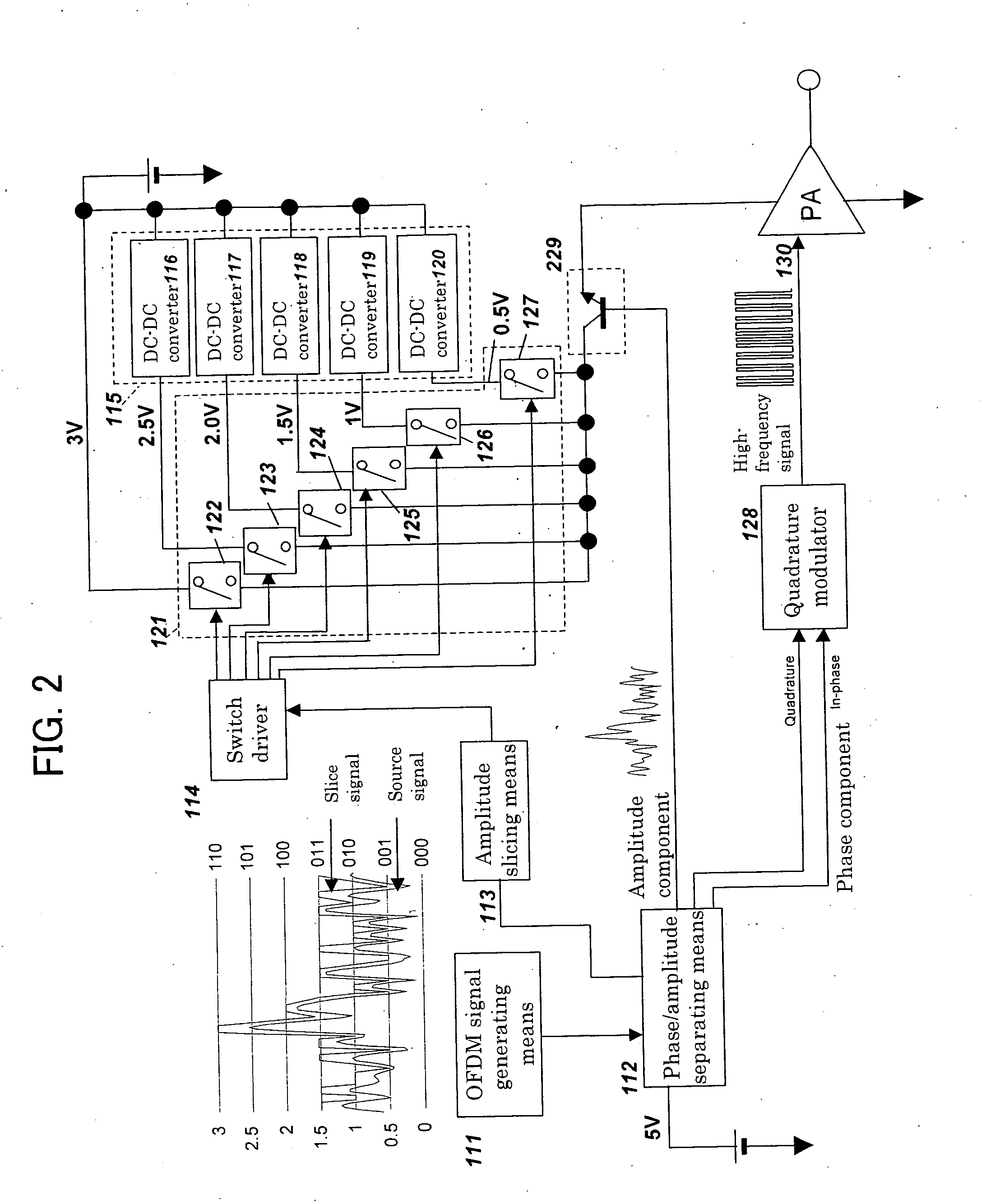
[0121]FIG. 2 is a block diagram of a transmitter in accordance with Embodiment 2 of the present invention. This embodiment differs from Embodiment 1 in that an emitter follower 229 is used instead of the series regulator 129. Except for this, this embodiment is the same as Embodiment 6 in configuration and operation; hence, the components are designated by the same numerals and their explanations are omitted. The emitter follower 229 receives the outputs of the switch group 121 at the collector and applies the power supply voltage to the high-frequency power amplifier 130 on the basis of the voltage of the phase / amplitude separating means 112 having been input to the base.
[0122] An effect additionally obtained by using the emitter follower 229 is described below. In the case of the series regulator, a sufficient frequency band is not obtained in some cases owing to a phase delay due to the feedback loop or the like. On the other hand, in the case of using the emitter follower 229, ...
embodiment 3
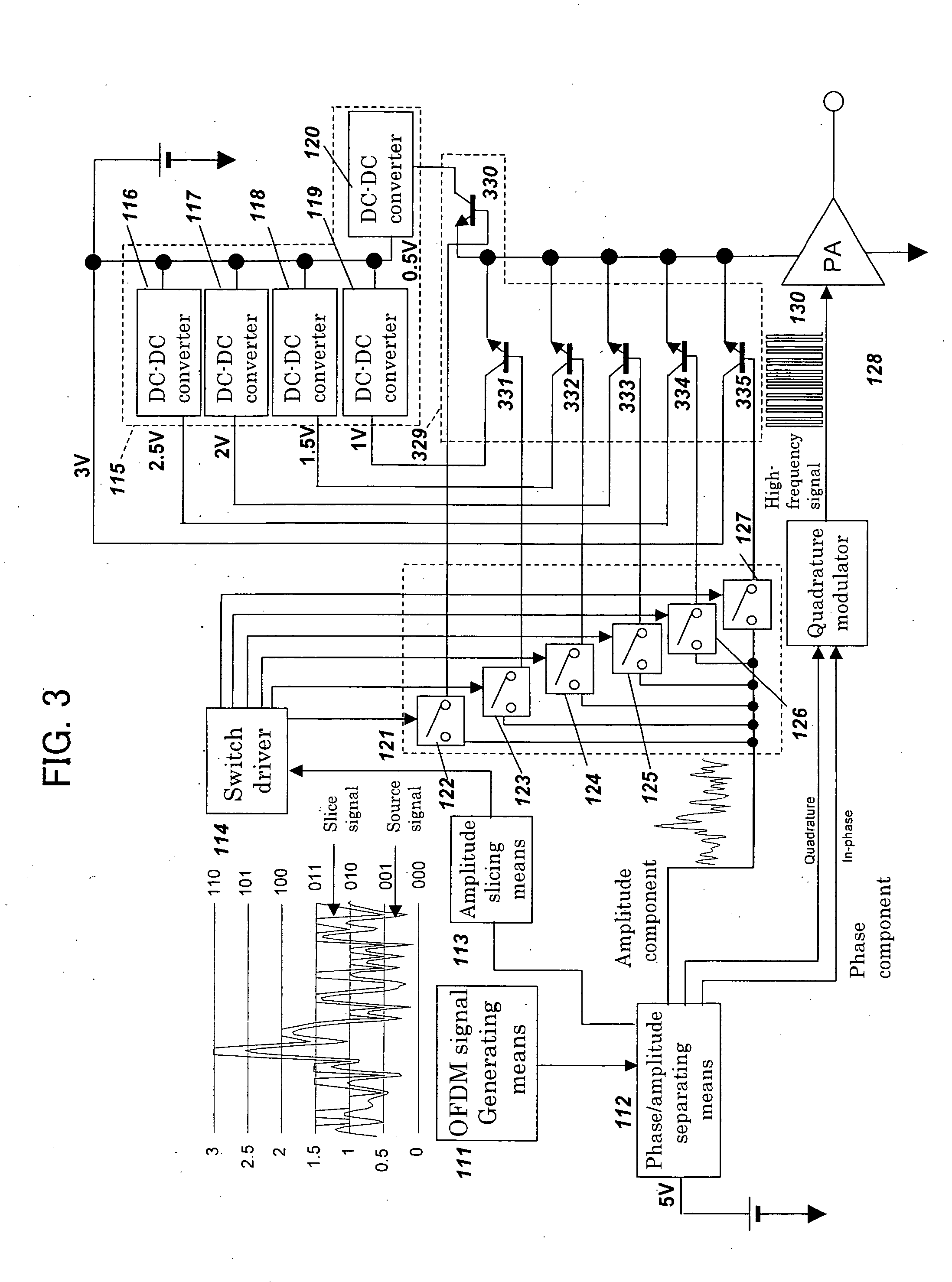
[0123]FIG. 3 is a block diagram of a transmitter in accordance with Embodiment 8 of the present invention. This embodiment differs from Embodiments 1 and 2 in that the outputs from the power supply and the DC-DC converter group 115 are directly connected to the collectors of an emitter follower group 329 as many as the outputs, and that the bus connected to the base terminals of this emitter follower group 329 is switched by the switch group 121 comprising switches as many as the emitter followers of the emitter follower group 329. The same components as those of Embodiments 1 and 2 are designated by the same numerals and their explanations are omitted. The emitter follower group 329 corresponds to linear voltage converting means. It is preferable that the switch group 121 is formed of NMOS transistors. In addition, although this embodiment uses the plurality of emitter followers, an embodiment using series regulators instead of the emitter followers can also be devised in a way sim...
PUM
 Abstract
Description
Claims
Application Information
 - R&D
- Intellectual Property
- Life Sciences
- Materials
- Tech Scout
- Unparalleled Data Quality
- Higher Quality Content
- 60% Fewer Hallucinations
Browse by: Latest US Patents, China's latest patents, Technical Efficacy Thesaurus, Application Domain, Technology Topic, Popular Technical Reports.
© 2025 PatSnap. All rights reserved.Legal|Privacy policy|Modern Slavery Act Transparency Statement|Sitemap|About US| Contact US: help@patsnap.com


