Honeycomb structural body

Inactive Publication Date: 2006-04-13
IBIDEN CO LTD
View PDF46 Cites 81 Cited by
  • Summary
  • Abstract
  • Description
  • Claims
  • Application Information

AI Technical Summary

Benefits of technology

[0038] The honeycomb structural body (filter) of the present invention, which has a structure in which lamination members are laminated in the length direction so that the through holes are superposed on one another, with one of the ends of each through hole being sealed, makes it possible to improve the collecting efficiency. Moreover, since the flow of exhaust gases can be changed, deep-layer filtering processes in the inner side of the wall portion can be executed so that the pressure loss after particulate collection is reduced.
[0039] Moreover, in the honeycomb structural body, upon regenerating process, a great temperature difference occurs in the length direction of the filter due to burning processes of particulates to cause a great thermal stress on the filter; however, the honeycomb structural body of the present invention has a structure in which lamination members are laminated in the length direction so that, even when a great temperature difference occurs in the entire filter, a temperature difference occurring in each of the lamination members is comparatively small and the resulting thermal stress is also small, thereby making the honeycomb structural body less likely to be damaged. Consequently, even continuous regenerating processes can be carried out on the honeycomb structural body of the present invention and thus the honeycomb structural body can be used for a long time. Moreover, in the case where the filter is designed to have a complex shape, a uniform temperature response tends to be disturbed to cause a temperature difference in the filter, making the filter very weak to the thermal stress; however, even when formed into a complex shape, the honeycomb structural body of the present invention is less likely to be damaged.
[0040] Moreover, since the honeycomb structural body of the present invention has a structure in which lamination members are laminated in the length direction, it is possible to freely change the amount of deposition of the catalyst in the length direction and the kind of the catalyst in accordance with the application. Consequently, the honeycomb structural body of the present invention makes it possible to improve the regenerating process and purifying functions for toxic gases. In this case, it is not necessarily required to have the structure in which one of the ends of each through hole is sealed in the honeycomb structural body.
[0041] Here, in the honeycomb structural body of the present invention, it is possible to easily form irregularities on the surface of the wall portion of the honeycomb structural body by laminating lamination members having different shapes and/or sizes of the through holes alternat

Problems solved by technology

Recently, particulates, such as soot, contained in exhaust gases that are discharged from internal combustion engines of vehicles, such as buses and trucks, and construction machines, have raised serious problems as those particulates are harmful to the environment and the human body.
However, when the above-mentioned methods are used in the porous ceramic honeycomb structural body made from refractory particles, the strength of the filer becomes very low.
For this reason, upon burning and removing collected particulates (hereinafter, referred to as a regenerating process) in such a filter, the filter tends to generate a great temperature difference in the length direction of the filter due to the burning process of the particulates, resulting in damages such as cracks in the filter due to the resulting thermal stress.
Although the honeycomb structural body using the metal porous material is capable of maintaining sufficient strength even when the porosity is increased, the filtering area becomes very small because of its st

Method used


Image

  • Honeycomb structural body
  • Honeycomb structural body
  • Honeycomb structural body

Examples


example 1

(1) Manufacturing Process of Lamination Members

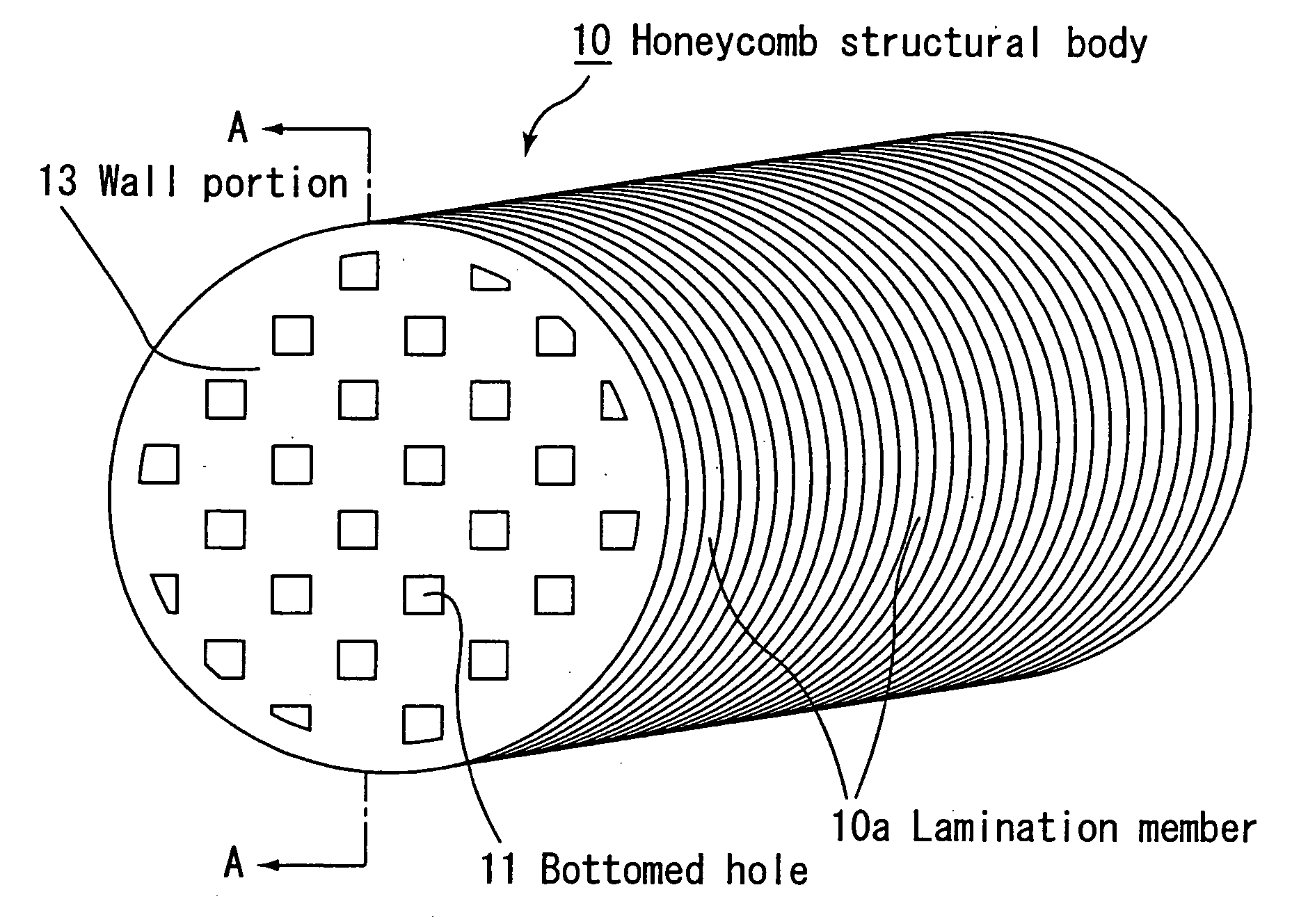
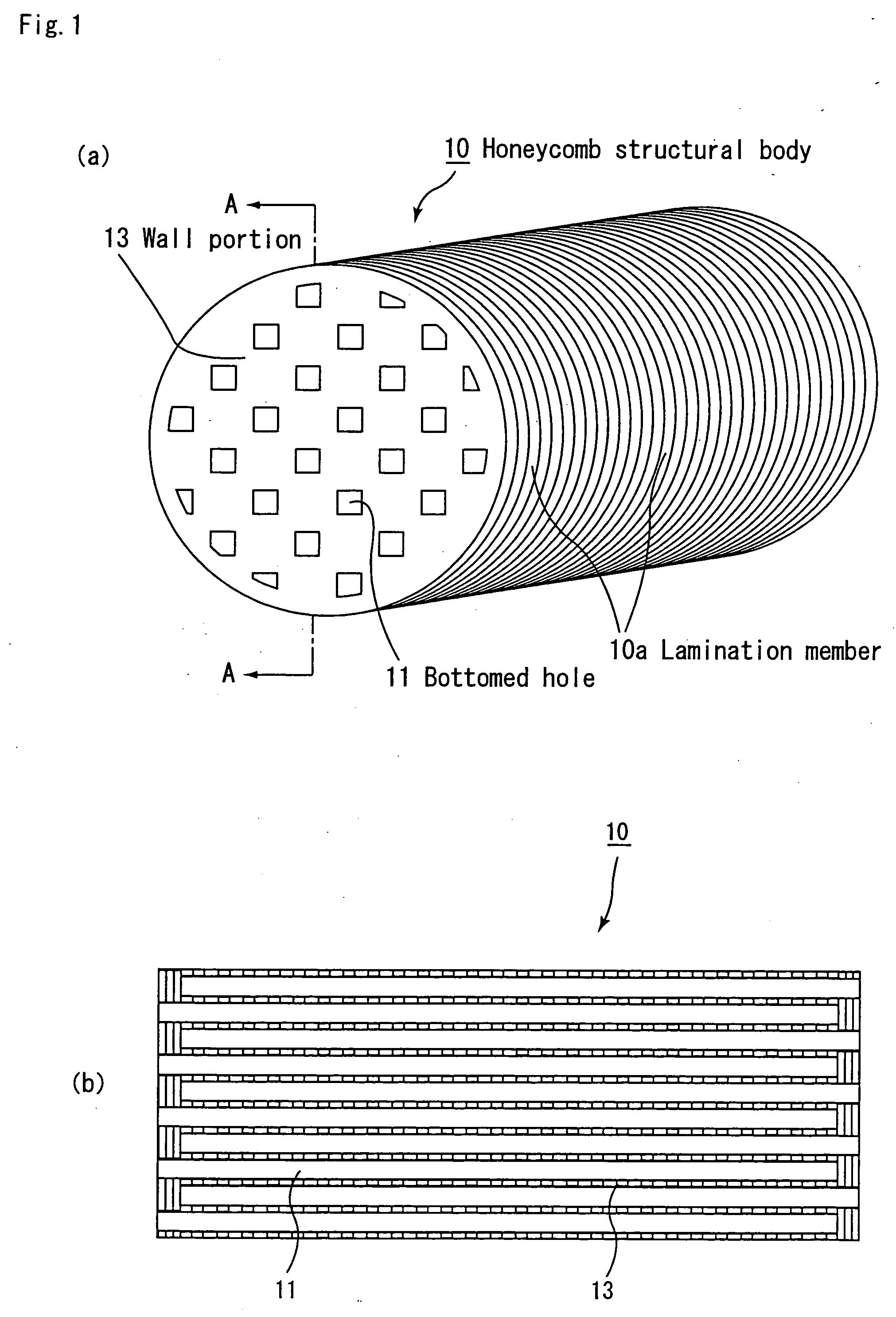
[0145] A three-dimensional mesh-shape porous member, made of Ni—Cr alloy (trade name: CELMET, average pore diameter: 400 μm, made by Sumitomo Electric Industries Ltd.), was compressed by a roller so as to have an average pore diameter of 80 μm, and after having been machined into a disc shape having a size of 43.8 mm in diameter×1 mm in thickness, the resulting disc is machined by laser to form holes, each having a size of 6 mm×6 mm, over the almost entire surface with mutual intervals of 2 mm; thus, a lamination member A1 having a honeycomb shape was manufactured.

[0146] Moreover, in order to form members for use in two end portions of the honeycomb structural body, a three-dimensional mesh-shape porous member, made of Ni—Cr alloy (trade name: CELMET, average pore diameter: 400 μm, made by Sumitomo Electric Industries Ltd.), was compressed by a roller so as to have an average pore diameter of 80 μm, and after having been machined int...

example 2

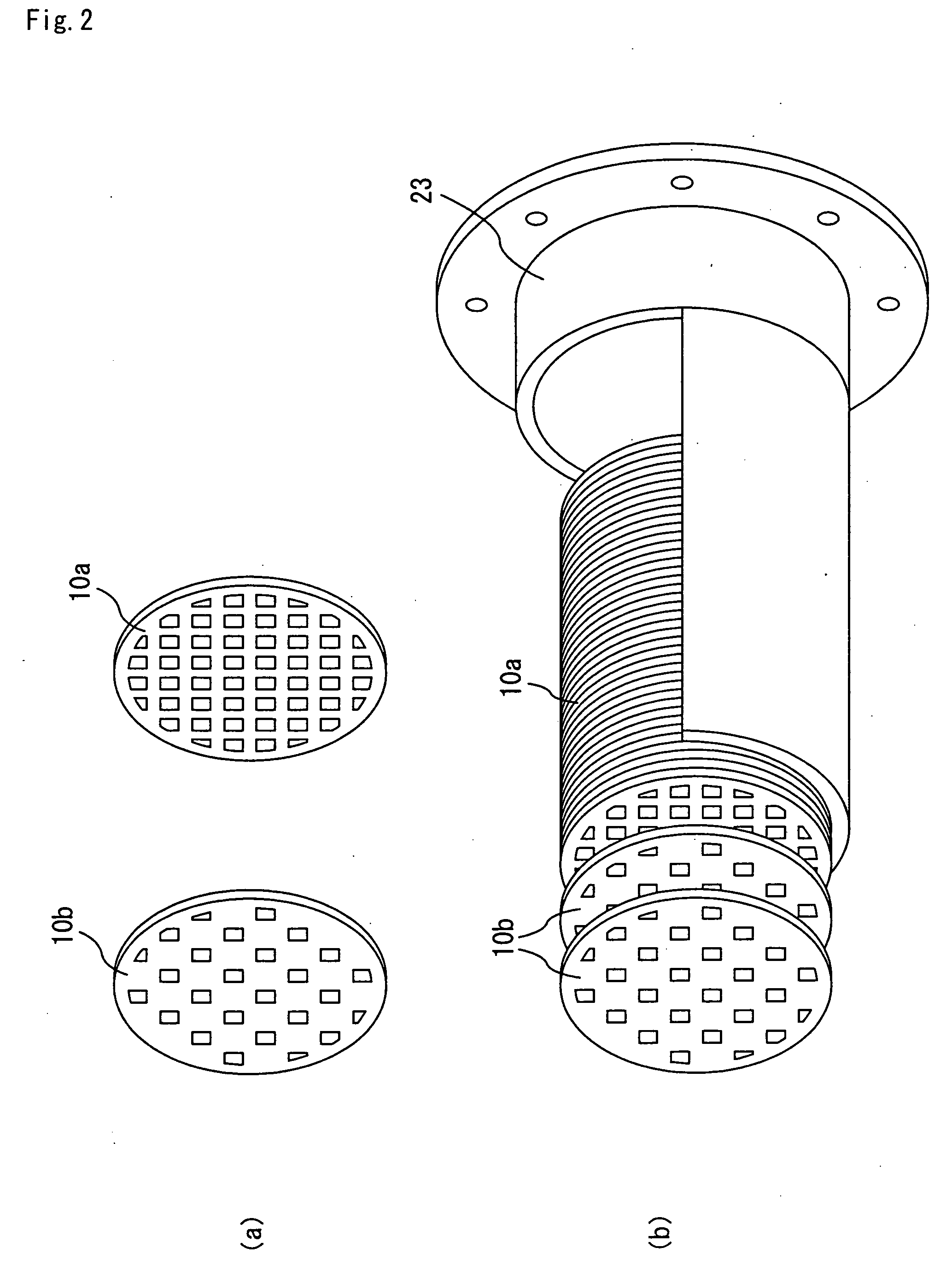
[0151] A three-dimensional mesh-shape porous member, made of Ni—Cr alloy (trade name: CELMET, average pore diameter: 400 μm, made by Sumitomo Electric Industries Ltd.), was compressed by a roller so as to have an average pore diameter of 80 μm, and after having been machined into a disc shape having a size of 143.8 mm in diameter×1 mm in thickness, the resulting disc is machined by laser to manufacture a lamination member A2 having a honeycomb shape with a thickness of 2 mm in the same manner as the lamination member A1; then, the same processes as Example 1 were carried out except that after having applied a catalyst thereto, five of the lamination members B1, 70 of the lamination members A2 and five of the lamination members B1 were laminated in this order so that an exhaust gas purifying device in which a honeycomb structural body having a length of 150 mm was assembled into a casing was prepared.

example 3

[0152] A three-dimensional mesh-shape porous member, made of Ni—Cr alloy (trade name: CELMET, average pore diameter: 400 μm, made by Sumitomo Electric Industries Ltd.), was compressed by a roller so as to have an average pore diameter of 80 μm, and after having been machined into a disc shape having a size of 143.8 mm in diameter×4 mm in thickness, the resulting disc is machined by laser to manufacture a lamination member A3 having a honeycomb shape with a thickness of 4 mm in the same manner as the lamination member A1; then, the same processes as Example 1 were carried out except that after having applied a catalyst thereto, five of the lamination members B1, 35 of the lamination members A3 and five of the lamination members B1 were laminated in this order so that an exhaust gas purifying device in which a honeycomb structural body having a length of 150 mm was assembled into a casing was prepared.


PUM

PropertyMeasurementUnit
Lengthaaaaaaaaaa
Sizeaaaaaaaaaa

Abstract

An object of the present invention is to provide a honeycomb structural body for use in a filter, which can support a large amount of catalysts, can suppress increase in pressure loss upon collecting particulates, can have a high particulate collecting capability and can efficiently carry out a regenerating process and a toxic gas purifying process. The honeycomb structural body according to the present invention is a pillar-shaped honeycomb structural body having a structure in which a plurality of through holes are placed in parallel with one another in the length direction with a partition wall interposed therebetween, wherein lamination members are laminated in the length direction so that the through holes are superposed on one another, and one of ends of each through hole is sealed.

Description

TECHNICAL FIELD [0001] This application claims benefit of priority to Japanese Patent Application No. 2003-197385, filed on Jul. 15, 2003, and Japanese Patent Application No. 2003-376227, filed on Nov. 5, 2003, the contents of which are incorporated by reference herein. [0002] The present invention relates to a honeycomb structural body that is used in order to remove particulates, etc. contained in exhaust gases discharged from an internal combustion engine such as a diesel engine. BACKGROUND ART [0003] Recently, particulates, such as soot, contained in exhaust gases that are discharged from internal combustion engines of vehicles, such as buses and trucks, and construction machines, have raised serious problems as those particulates are harmful to the environment and the human body. Conventionally, various filters, which are used for collecting particulates in exhaust gases so as to purify the exhaust gases, have been proposed, and filters having a honeycomb structure have also be...

Claims


Application Information

Patent Timeline
IPC IPC(8): B01D46/00B01D39/20B01D46/24B01D53/86B01J23/63B01J35/04B01J37/02C04B38/00F01N3/022F01N3/28
CPCB01D39/2027Y10T428/24149B01D46/0024B01D46/2418B01D46/2455B01D46/2459B01D46/2462B01D46/2466B01D53/9454B01D2046/2492B01J23/63B01J35/04B01J37/0225B01J37/0242C04B38/0006C04B2111/00793C04B2111/0081F01N3/0222F01N3/2828F01N2330/06F01N2330/48B01D39/2082Y02T10/22Y02T10/20Y10S55/30Y10S55/10C04B35/565Y02T10/12B01D46/2486B01D46/64B01D46/248F01N3/02
Inventor OHNO, KAZUSHIGEKUNIEDA, MASAFUMI
Owner IBIDEN CO LTD
Why Eureka
Try Eureka