
Alloy containing rare earth element, production method thereof, magnetostrictive device, and magnetic refrigerant material

a technology of rare earth elements and magnetostrictive devices, which is applied in the selection of device materials, lighting and heating apparatuses, and magnetic bodies, etc. it can solve the problems of ggg not being used in a commercial product, compound cannot be applied to the magneto-displacement devices for controlling minute displacement, and the generated displacement is difficult to control. achieve the effect of high efficiency, low cost and reliable production

Inactive Publication Date: 2006-04-13
ERASTEEL
View PDF6 Cites 55 Cited by
  • Summary
  • Abstract
  • Description
  • Claims
  • Application Information

AI Technical Summary

Benefits of technology

[0023] In addition, an object of the present invention is to provide an RE-containing alloy powder which is easily pulverizable, is not too brittle, and can be produced at low cost, within a short time, and without increasing the oxygen content of the RE-containing alloy powder or a sintered product of the alloy which is employed as a magnetic refrigerant or a magnetostrictive material.
[0052] According to the present invention, there can be provided a technique capable of producing an NaZn13-type RE-containing alloy at high efficiency without performing long-term heat treatment; an NaZn13-type RE-containing alloy produced through the technique; and a magnetostrictive device and a magnetic refrigerant obtained from the NaZn13-type RE-containing alloy.

Problems solved by technology

However, these intermetallic compounds generate only minute displacement, and precise control of the generated displacement is difficult.
Therefore, these compounds cannot be applied to magneto-displacement devices for controlling minute displacement.
However, GGG has not yet been used in a commercial product, because of its poor refrigeration efficiency upon application of a weak magnetic field provided by a permanent magnet.
In the conventional method for producing NaZn13-type RE-containing alloys, the long-term heat treatment step for removing an undesired phase lowers productivity and increases costs in the production of NaZn13-type RE-containing alloys, devices employing the alloys, and other products employing the alloys.
However, the aforementioned conventional method for producing an RE-containing alloy powder has a drawback.
Namely, since the method includes a long-term heat treatment and two melting steps, production costs increase and oxygen content of the alloy increases, even though low-cost material is used.

Method used


Image

  • Alloy containing rare earth element, production method thereof, magnetostrictive device, and magnetic refrigerant material
  • Alloy containing rare earth element, production method thereof, magnetostrictive device, and magnetic refrigerant material
  • Alloy containing rare earth element, production method thereof, magnetostrictive device, and magnetic refrigerant material

Examples


example 1

[0132] Metallic La (serving as a source of rare earth metal (R)), electrolytic iron (serving as a source of transition metal (T)), and metallic Si (serving as a source of element (A)) were weighed and mixed such that an alloy composition of La(Fe0.88Si0.12)13 was attained. The mixture was melted in an Ar atmosphere at 0.1 MPa, by means of heating to 1,600° C.

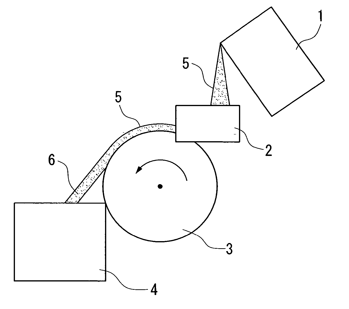
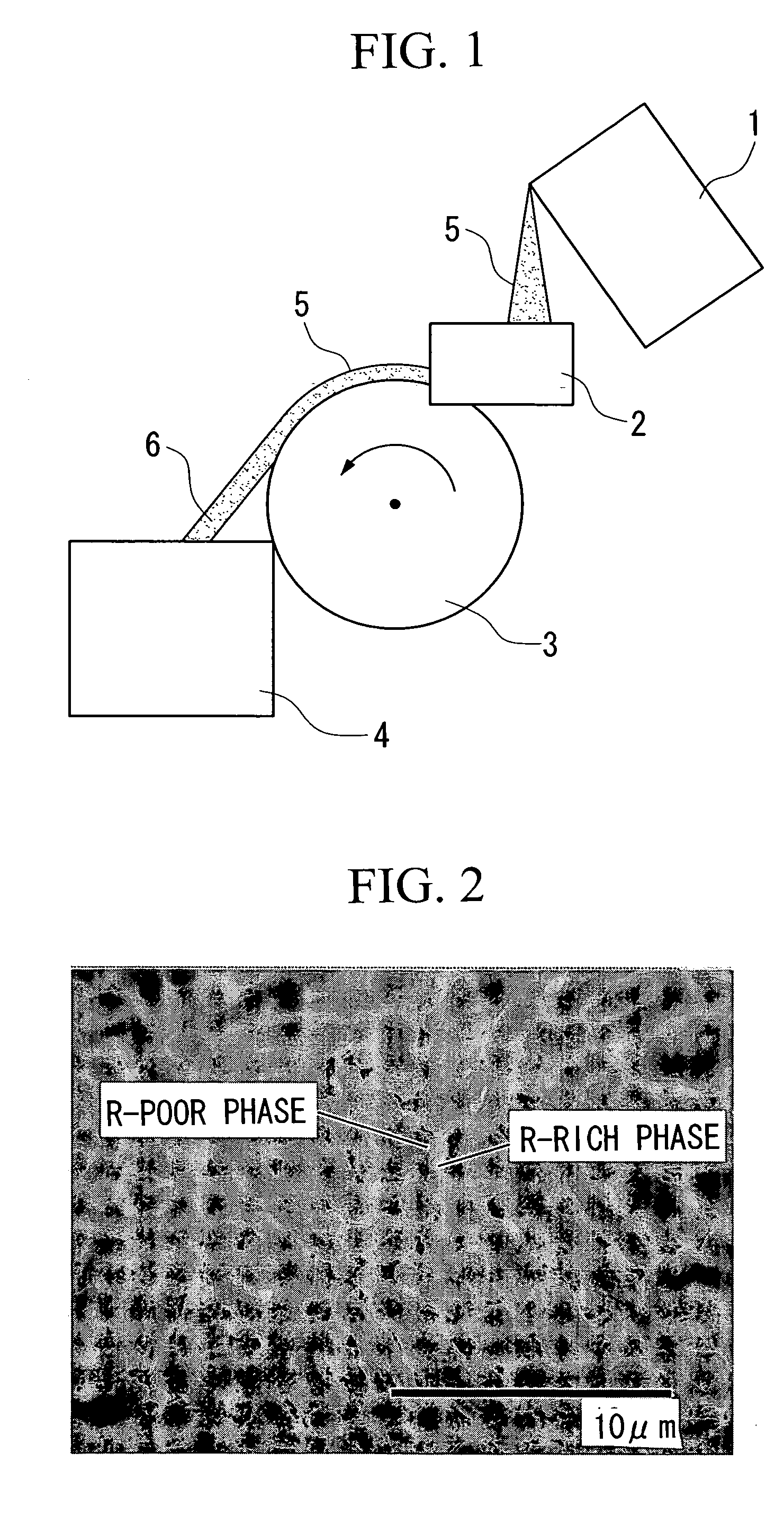
[0133] Subsequently, by means of a strip casting apparatus shown in FIG. 1, the molten metal was poured, onto a copper roller which was cooled with water and rotating at a rotating speed of 0.882 m / s, at a pour rate of 150 g / s and a width of 85 mm, to thereby rapidly quench the molten metal, whereby alloy strips having a thickness of 0.28 mm were produced. The cooling rate as measured within a range of 1,600 to 900° C. was found to be approximately 1×10³° C. / sec.

[0134]FIGS. 10 and 11 are back-scattered electron images of a cross-section of a sample of the produced alloy strips. The image of FIG. 11 is an enlarged image of FIG....

example 2

[0142] Metallic La (purity: ≧98 mass %) (6.5 at. %), pure iron (purity: ≧99 mass %) (83.2 at. %), and metallic Si (purity: ≧99.99 mass %) (10.3 at. %) were melted under Ar, and the molten alloy was cast through strip casting, to thereby produce alloy strips having a thickness of 0.25 mm. Subsequently, the thus-cast La—Fe—Si alloy was heated in a vacuum at 1,100° C. for 12 hours.

[0143] The thus-produced La—Fe—Si alloy was pulverized by means of a disk mill, and the formed powder was classified by use of a sieve (100 μm). The pulverization efficiency was found to be 1.2 kg / h. Subsequently, the thus-produced powder was compacted in a nitrogen atmosphere at a compacting pressure of 1.0 t / cm2. The compact was sintered in a vacuum at 1,280° C. for three hours, followed by heating at 1,100° C. for 12 hours, to thereby produce sintered La(Fe0.89Si0.11)13 alloy.

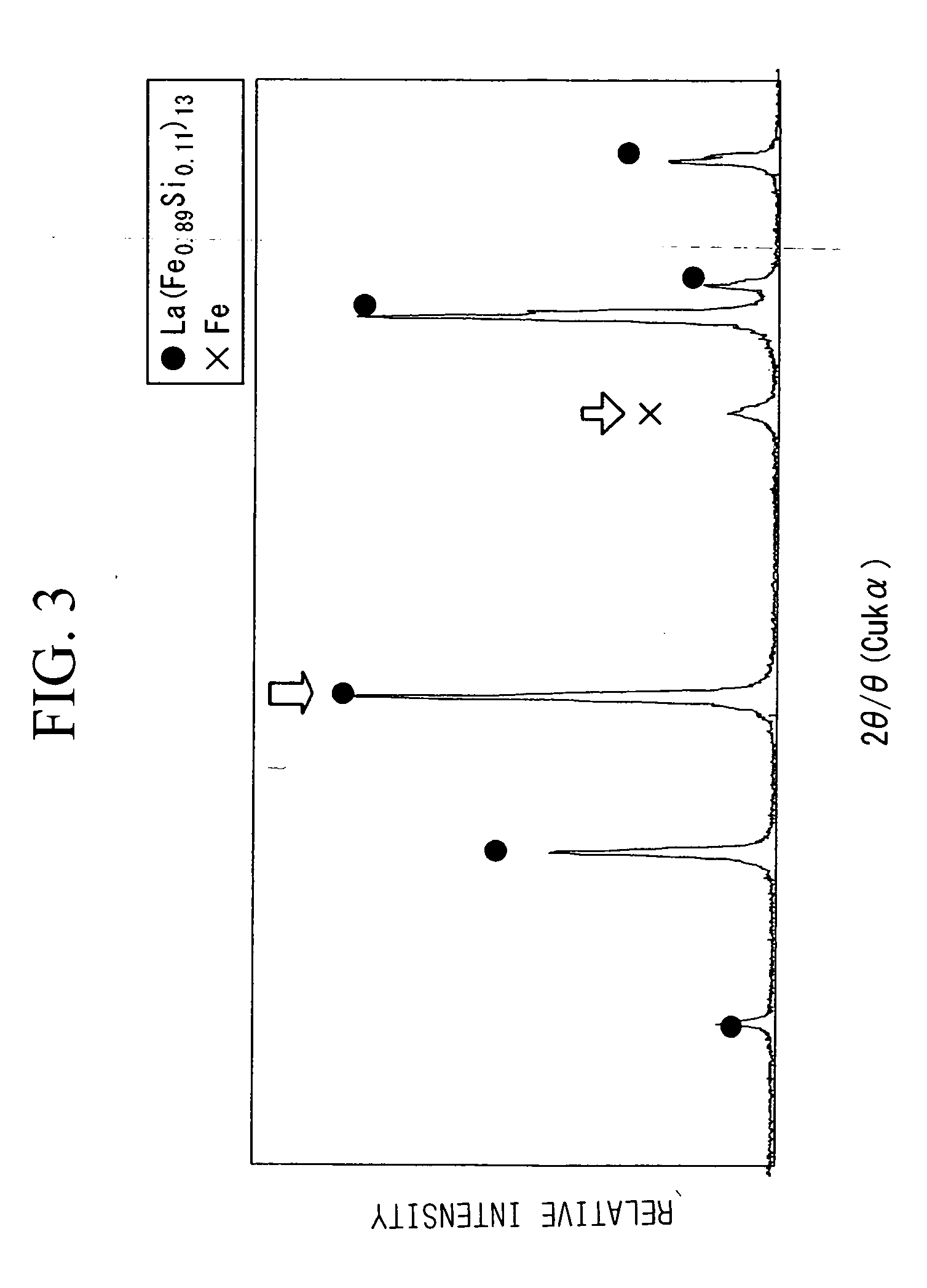
[0144] X-ray diffractometry of the sintered alloy shows that the relative peak intensity of La(Fe0.89Si0.11)13 alloy, having NaZn1...


PUM

PropertyMeasurementUnit
Temperatureaaaaaaaaaa

Abstract

A method for producing an RE-containing alloy represented by formula R(T1−xAx)13−y (wherein R represents Ce, etc.; T represents Fe, etc.; and A represents Al, etc; 0.05≦x≦0.2; and −1≦y≦1) including a melting step of melting alloy raw materials at 1,200 to 1,800° C.; and a solidification step of rapidly quenching the molten metal produced through the above step, to thereby form the first RE-containing alloy, wherein the solidification step is performed at a cooling rate of 102 to 104° C. / second, as measured at least within a range of the temperature of the molten metal to 900° C.; and an RE-containing alloy, which is represented by a compositional formula of RrTtAa(wherein R and A represent the same meaning as above, T represents Fe, etc.; 5.0 at. %≦r≦6.8 at. %, 73.8 at. %≦t≦88.7 at. %, and 4.6 at. %≦a≦19.4 at. %) and has an alloy microstructure containing an NaZn13-type crystal structure in an amount of at least 85 mass % and α-Fe in an amount of 5-15 mass % inclusive.

Description

CROSS-REFERENCE TO RELATED APPLICATIONS [0001] This application claims the benefit pursuant to 35 U.S.C. §119(e)(1) of U.S. Provisional Applications, No. 60 / 424,015 filed Nov. 6, 2002 and No. 60 / 488,095 filed Jul. 18, 2003.TECHNICAL FIELD [0002] The present invention relates to a method for producing an alloy containing a rare earth element (hereinafter referred to as RE-containing alloy), to an RE-containing alloy, to a method for producing an RE-containing alloy powder, to an RE-containing alloy powder, to a method for producing a sintered RE-containing alloy, to a sintered RE-containing alloy, to a magnetostrictive device, and to a magnetic refrigerant. More particularly, the invention relates to a technique for producing an NaZn13-type RE-containing alloy which is suitable for producing a magnetostrictive device, a magnetic refrigerant, etc. BACKGROUND ART [0003] Magnetostrictive devices, which generate strain through application of a magnetic field, are employed as magnetostric...

Claims


Application Information

Patent Timeline
IPC IPC(8): H01F1/055B22D11/00B22D11/06B22D11/106C21D6/00C21D8/12C22C1/04C22C33/04C22C38/00C22C38/02F25B21/00H01F1/01H01F1/057H01F41/02H01L41/20
CPCB22D11/001B22D11/0611B22D11/106B22F2009/041B22F2998/00B22F2998/10B22F2999/00C21D6/00C21D8/1211C22C1/0441C22C38/005C22C38/02F25B21/00H01F1/015H01F1/0551H01F1/0577H01F1/058H01F41/0266H01L41/20Y02B30/66B22F3/24B22F9/008B22F9/04B22F3/10B22F2003/241B22F2201/013C22C1/0491C22C33/0278B22F3/02Y02B30/00H10N35/85C22C1/047
Inventor NAKAJIMA, KENICHIRO
Owner ERASTEEL
Learn More