
Photothermographic imaging material and method for forming image

a technology of photothermographic imaging and material, applied in the field can solve the problems of uneven density, transport failure, and varying density of photothermographic imaging material with time, and achieve excellent light radiated image stability and silver color tone, excellent image storage stability, and high density

Inactive Publication Date: 2006-04-20
KONICA MINOLTA INC
View PDF2 Cites 0 Cited by
  • Summary
  • Abstract
  • Description
  • Claims
  • Application Information

AI Technical Summary

Benefits of technology

The present invention provides a photothermographic imaging material with high density and excellent image stability, especially in terms of color tone and rapid thermal development suitability. The material also has good film transportability and environmental suitability. The invention also provides a method for forming an image using the material. The technical effects of the invention include improved image quality, higher sensitivity, and better thermal development performance.

Problems solved by technology

In the meanwhile, there has been problematic in that slipping property between the imaging material and a transport roller or processing members of the thermal developing apparatus changes, and transport failure and density unevenness occur.
Also there has been problematic in that the density of the photothermographic imaging material varies with time.
For downsizing the thermal development processing apparatus, it is more advantageous to use a heat drum mode than to use a horizontal transport mode, but there has been problematic in that powder drop off, density unevenness and roller mark easily occur at the thermal development processing.
However, when these technologies were used, there was problematic in that density changes (printout property) with time after the thermal development processing became large and the silver color tone became extremely different (took on a yellow tinge) compared to wet type-X-ray films in earlier technology.
Additionally, a new problem where the color tone takes on a red tinge at high density areas with density of 2.0 or more has occurred when those with smaller average particle size are used as the silver halide.
A silver ion reducing agent, a compound which forms a complex with the silver ions, a compound which bleaches fine silver nuclei which become sources of photographic fog which produces on surfaces of silver halide grains, and the like are contained in the silver salt photothermographic dry imaging material, and thus it is not easy to control developed silver shapes and retain images after the thermal development.
However, the color tone in the image storage is improved, but the color tone immediately after the thermal development is not improved.
Also, proposed are the improvement methods by activating photothermographic property by contrivance of fatty acid silver salt crystal structures (e.g., see JP-A-2002-23303 and JP-A-2002-49119), but it can not help being said that all the methods are at insufficient levels in terms of realizing the stable silver color tone.
However, the technology described in JP-A-2002-169249 is more excellent in improvement level of the color tone compared to the above technology which controls the developed silver shape, but has disadvantages that the photographic fog and deterioration of the color tone changes frequently occur in the long term storage and in the image storage probably because produced dyestuffs are unstable and further adversely affect the silver halide.

Method used


Image

  • Photothermographic imaging material and method for forming image
  • Photothermographic imaging material and method for forming image
  • Photothermographic imaging material and method for forming image

Examples


examples

[0409] Hereinafter, the present invention is described in detail by examples, but the embodiments of the invention is not limited thereto. In addition “%” in the Examples represents “% by mass” when there is no special notice.

example a-1

[0410] Corona discharge treatment at 8W / m2·min was given to both faces of a commercially available PET film with thickness of 175 μm and optical density of 0.170 (measured by a densitometer PDA-65 supplied from Konica Corporation) biaxially stretched and thermally fixed which was colored with the following blue dye, the following under coating solution a-1 was applied on one side face such that the thickness of dried film is 0.8 μm, and was dried to make an under coating layer A-1. Also, the following under coating solution b-1 was applied on an opposite side face such that the thickness of dried film is 0.8 μm, and was dried to make an under coating layer B-1.

(Under coat coating solution a-1)Copolymer latex solution of butyl acrylate / t-butyl270 gacrylate / styrene / 2-hydroxyethyl acrylate (30 / 20 / 25 / 25%ratio) (solid content 30%)(C-1) 0.6 gHexamethylene-1,6-bis(ethylene urea) 0.8 gare filled up with water to 1 L.(Under coat coating solution b-1)Copolymer latex solution of butyl acryla...

example b-1

>

[0452] Corona discharge treatment at 0.5 kV·A·min / m2 was given to one side face of a polyethylene terephthalate film base (thickness 175 μm) blue-colored at a density of 0.170, and then using the following under coat coating solution A, an under coating layer a was applied on it such that the thickness of dried film became 0.2 μm. The corona discharge treatment at 0.5 kV·A·min / m2 was similarly given to another face, and then using the following under coat coating solution B, an under coating layer b was applied on it such that the thickness of dried film became 0.1 μm. Subsequently, heat treatment was carried out at 130° C. for 15 min in a heat treating type oven having a film transport apparatus made up of multiple roller groups to make a support.

(Preparation of Under Coat Coating Solution A)

[0453] Copolymer latex solution (270 g) of 30% of n-Butyl acrylate, 20% of t-butyl acrylate, 25% of styrene and 25% of hydroxyethyl acrylate by mass (solid content 30% by mass), 0.6 g of su...


PUM

PropertyMeasurementUnit
mol %aaaaaaaaaa
mol %aaaaaaaaaa
optical densityaaaaaaaaaa

Abstract

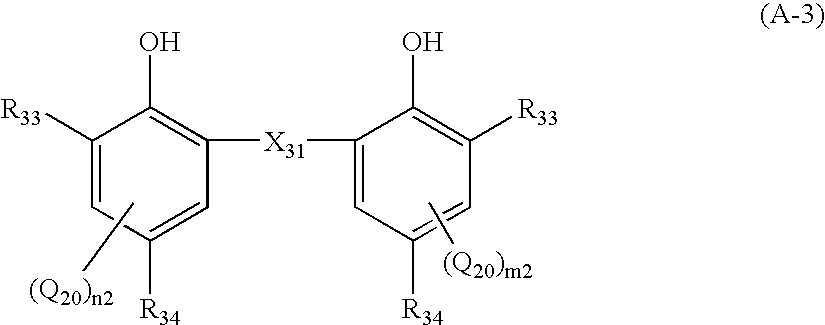
A photothermographic imaging material including a support; an image forming layer containing an organic silver salt, a photosensitive silver halide, a binder and a silver ion reducing agent, the image forming layer being provided on the support; and a cyan coloring leuco dye. The photosensitive silver halide contains silver halide grains having a mean particle size of 10 to 50 nm, and the silver ion reducing agent is a compound represented by the following Formula (A-3).

Description

CROSS REFERENCE TO RELATED APPLICATIONS [0001] This application is a Division of U.S. patent application Ser. No. 10 / 727,313, filed Dec. 2, 2003, which, in turn, claims the priority of Japanese Patent Application Nos. JP2002-356615 filed Dec. 9, 2002 and 2003-005526 filed Jan. 14, 2003, the priority of which are all claimed.BACKGROUND OF THE INVENTION [0002] 1. Field of the Invention [0003] The present invention relates to a photothermographic imaging material, and particularly to a photothermographic imaging material with high density which is excellent in light radiated image stability, silver color tone and the like, and to a method for forming an image by using the same. [0004] 2. Description of Related Art [0005] Recently, in the fields of medical care and print plate making, waste solutions involved in wet processings of image formation materials have been problematic in terms of working property, and reduction of processing waste solutions has been strongly desired in the lig...

Claims


Application Information

Patent Timeline
Patent Type & Authority Applications(United States)
IPC IPC(8): G03C1/00G03C1/30G03C1/498G03C5/02
CPCG03C1/30G03C1/49809G03C1/49818G03C1/49827G03C1/49845G03C1/49863G03C1/49881G03C5/02G03C1/04G03C2001/03558G03C2001/03564G03C2007/3025G03C2001/03594G03C2200/39G03C7/3041G03C2200/26
Inventor KASHIWAGI, HIROSHIGOTO, NARITO
Owner KONICA MINOLTA INC
Learn More