Silicon microphone with softly constrained diaphragm

a silicon microphone and diaphragm technology, applied in the direction of transducer diaphragms, semiconductor electrostatic transducers, instruments, etc., can solve the problems of significant affecting the compliance of the silicon microphone diaphragm, the diaphragm can either buckle or become stiff, and the intrinsic stress is not known. , to achieve the effect of reducing the intrinsic stress

Active Publication Date: 2006-05-04
SHANDONG GETTOP ACOUSTIC
View PDF5 Cites 97 Cited by
  • Summary
  • Abstract
  • Description
  • Claims
  • Application Information

AI Technical Summary

Benefits of technology

[0009] One objective of the present invention is to provide a sensing element of a silicon microphone wherein a diaphragm is softly constrained in order to reduce an intrinsic stress therein.
[0010] A further objective of the present invention is to provide a simple fabrication method of forming a sensing element in a silicon condenser microphone according to the first objective.
[0011] A still further objective of the present invention is to provide a method of forming a sensing element of a silicon microphone according to the second objective that is cost effective.
[0012] These objectives are achieved with a silicon microphone sensing element which features a circular or square diaphragm with an edge constrained by a soft polymeric material. The soft polymer constraint is strong enough to hold the diaphragm in place during a vibrational mode and is connected to a rigid supporting layer that is anchored to a substrate. Furthermore, the soft polymer constraint is able to relieve the intrinsic stress in the diaphragm which is typically a thin film of polysilicon. Just like button fasteners, the soft polymer constraint joins the diaphragm and the rigid supporting layer near the edge of the diaphragm. Having a Young's modulus substantially lower than that of the diaphragm, the soft polymer constraint is able to relieve the intrinsic stress in the diaphragm. The diaphragm is separated by an air gap from an underlying substrate having a front side with a backplate region with acoustic holes formed therein. A back hole is formed below the backplate region from the back side of the substrate. Furthermore, there is a rectangular shaped electrical lead-out arm extending from the diaphragm edge. The lead-out arm is attached to an overlying first electrode which is used to establish a variable capacitor circuit. There is a second electrode that is electrically connected to the substrate through the rigid supporting layer. After a sound signal strikes the diaphragm, a vibration is induced that changes the capacitance in the variable capacitor circuit.

Problems solved by technology

For example, the uncertain intrinsic stress associated with the deposition process for thin semiconductor films is problematic in the sense that it can significantly affect the compliance of the silicon microphone diaphragm.
If the stress is too high, the diaphragm can either buckle or become stiffened.
Since the diaphragm plays a key role in determining sensitivity and frequency response performance, the diaphragm must be as compliant as possible within a given frequency range which is difficult to achieve considering the intrinsic stress variation in thin films.
Unfortunately, the implementation of supporting springs requires some slot cuttings on the microphone diaphragm which introduces an acoustic leakage problem.
The fabrication of a thin diaphragm on a silicon substrate, as suggested by the prior art, is also a very challenging task for volume production.
However, the floating plate design requires a complex structural definition and a complicated fabrication method.
Moreover, it is difficult to ascertain where the diaphragm is anchored due to the gaps between the diaphragm and constraints following the sacrificial release and drying process.
However, even a small amount of bonding induced stress may still result in an uncertainty in mechanical compliance for a thin silicon membrane.
Unfortunately, it is difficult to control the strain gradient of the composite semiconductor membrane.
Moreover, the polymer coating and filling makes the strain gradient issue worse because of thermal expansion mismatching.

Method used


Image

  • Silicon microphone with softly constrained diaphragm
  • Silicon microphone with softly constrained diaphragm
  • Silicon microphone with softly constrained diaphragm

Examples


first embodiment

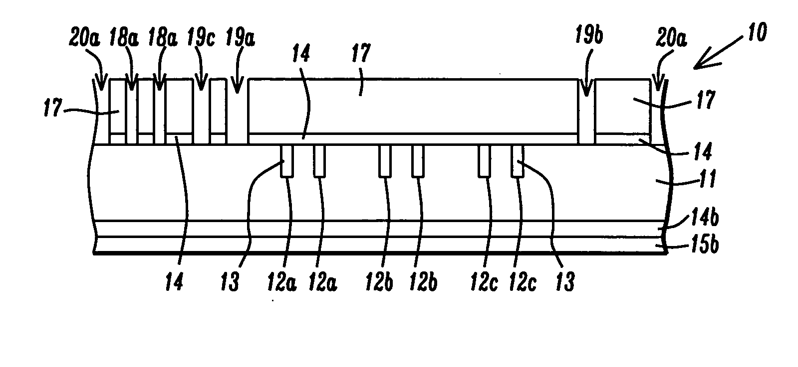
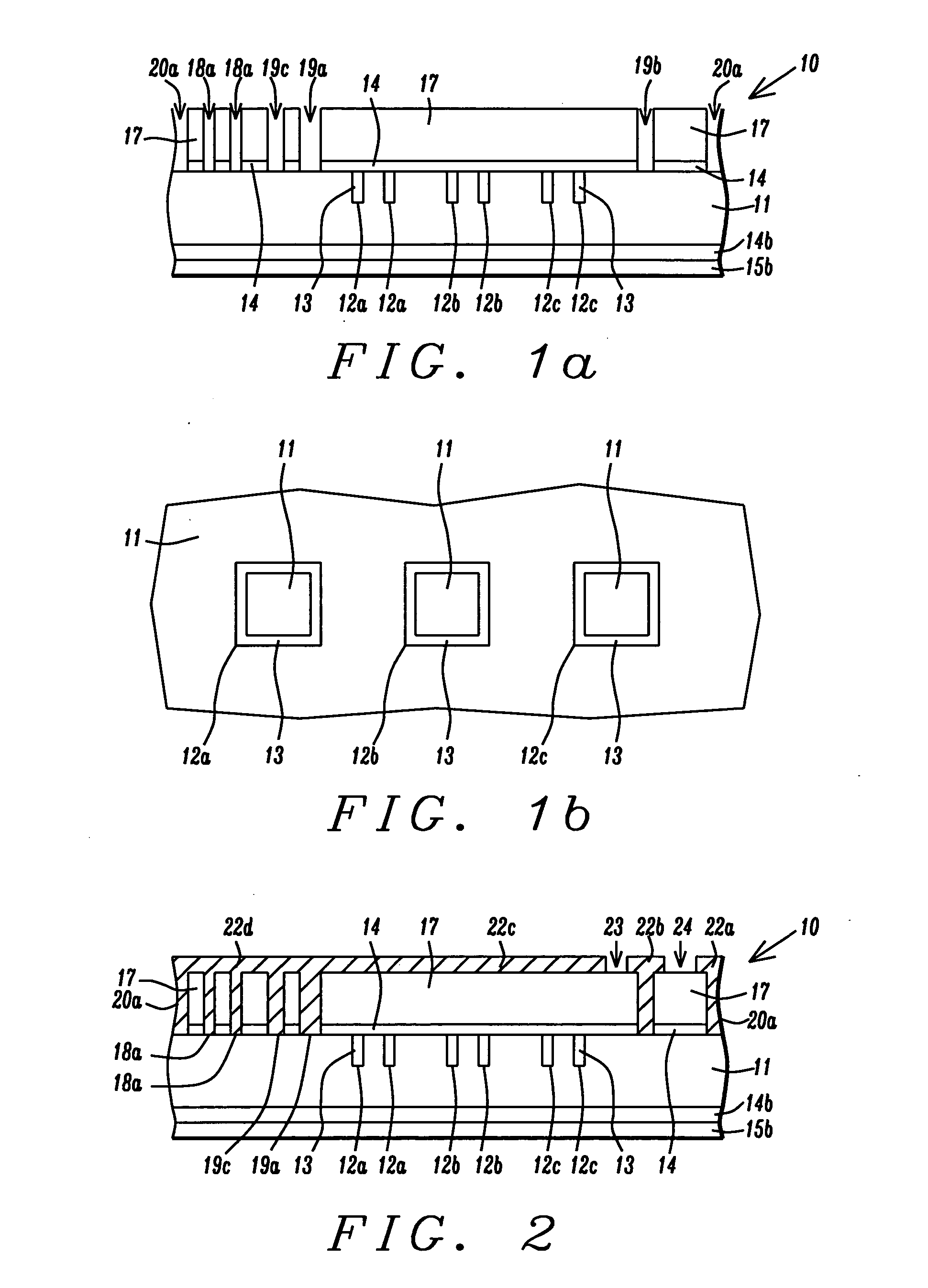
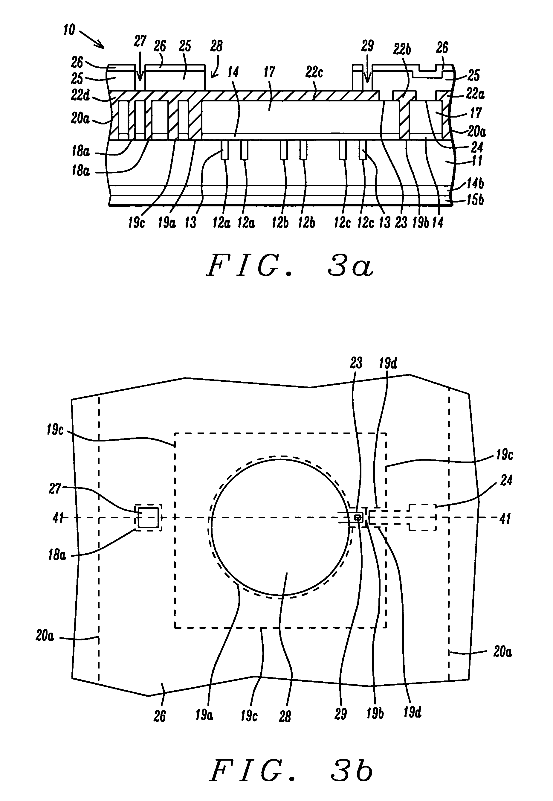
[0030] One embodiment of the silicon microphone sensing element according to the present invention will be described first and the novel process sequence used to form the first embodiment will be described in a later section. It is understood that a microphone sensing element based on a material other than silicon may be fabricated by alternative embodiments described herein. Referring to FIG. 7, a microphone sensing element 10 is constructed on a substrate 11 such as silicon which may have an n-type dopant and a resistivity as low as 0.01 ohms-m. The substrate 11 preferably has front and back sides that are polished. There is a thermal oxide layer 14 about 3000 Angstroms thick on the front side of substrate 11 and above the thermal oxide layer is a PSG layer 17 about 3.7 microns thick. The back side of substrate 11 has a stack of layers comprised of a lower thermal oxide layer 14b (about 3000 Angstroms thick) on the substrate and an upper PECVD silicon nitride layer 15b with a thic...

second embodiment

[0041] According to the present invention, there is a microphone sensing element 50 having a softly constrained diaphragm as depicted in FIGS. 15-17. Referring to FIG. 15, a microphone sensing element 50 is fabricated on a substrate 51 such as silicon which may have an n-type dopant and a resistivity as low as 0.01 ohms-cm. The substrate 51 preferably has front and back sides that are polished. Certain regions on the front side of the substrate 51 have trenches 52 filled with an oxide layer 54 that is about 2 microns thick above the trenches. Preferably, the trenches are aligned below an electrical lead-out arm 61c and first electrode 63 to be described in a later section. The oxide layer 54 and an overlying undoped first polysilicon (poly 1) layer 55 about 0.3 to 0.5 micron thick form a stack in the shape of one or more rectangular islands that cover the trenches 52 and a portion of the substrate 51 around the trenches. The oxide filled trenches serve to reduce substrate parasitic ...


PUM


Abstract

A microphone sensing element and a method for making the same are disclosed. The sensing element has a diaphragm and an attached electrical lead-out arm preferably made of polysilicon that are separated by an air gap from an underlying backplate region created on a conductive silicon substrate. The backplate region has acoustic holes created by removing an oxide filling in a continuous trench that surrounds hole edges and by removing oxide to form the air gap. The diaphragm is softly constrained along its edge by an elastic element that connects to a surrounding rigid polysilicon layer. The elastic element is typically a polymer such as parylene having a Young's modulus substantially less than that of the diaphragm. First and second electrodes are connected to the diaphragm through the lead-out arm and to the substrate through polysilicon via fillings, respectively, and thereby establish a variable capacitor circuit for acoustic sensing.

Description

FIELD OF THE INVENTION [0001] The invention relates to a sensing element of a silicon condenser microphone and a method for making the same, and in particular, to a microphone sensing element having a diaphragm that is constrained along its edges by an elastic polymer that relieves intrinsic stress and ensures maximum compliance for a desired frequency range. BACKGROUND OF THE INVENTION [0002] The silicon based condenser microphone also known as an acoustic transducer has been in a research and development stage for more than 20 years. Because of its potential advantages in miniaturization, performance, reliability, environmental endurance, low cost, and mass production capability, the silicon microphone is widely recognized as the next generation product to replace the conventional electret condenser microphone (ECM) that has been widely used in communication, multimedia, consumer electronics, hearing aids, and so on. Of all the designs, the capacitive condenser microphone has adva...

Claims


Application Information

Patent Timeline
Patent Type & Authority Applications(United States)
IPC IPC(8): H04R1/00H04R9/06
CPCH04R7/10H04R19/005H04R19/04H04R25/00H04R31/003
Inventor ZHE, WANGYUBO, MIAO
Owner SHANDONG GETTOP ACOUSTIC
Why Eureka
Try Eureka