
Float glass process for making thin flat glass and thin flat glass substrate made with same

a technology of float glass and flat glass, which is applied in the direction of glass rolling apparatus, manufacturing tools, transportation and packaging, etc., can solve the problems of undetectable thickness fluctuations and waviness of glass sheets, and it is not possible to make display glass with thickness,

Inactive Publication Date: 2006-05-25
SCHOTT AG
View PDF10 Cites 10 Cited by
  • Summary
  • Abstract
  • Description
  • Claims
  • Application Information

AI Technical Summary

Benefits of technology

[0012] It is an object of the present invention to provide a large surface or large area thin flat glass substrate, especially for display engineering, with a thickness of less than 1.5 mm, which meets high quality requirements, especially regarding permitted thickness variations.
[0013] It is also an object of the present invention to provide a process for making large area thin flat glass substrates, especially for display engineering, with a thickness of less than 1.5 mm and which have high quality, especially regarding thickness variations.
[0019] The thin flat glass substrate according to the invention fulfills the required high quality requirements as it comes from the float plant, i.e. without subsequent polishing. If a polishing is still required for any reason, it can be performed especially economically and / or efficiently, since the polishing work is kept very small because of the high surface quality of the product coming from the float plant.
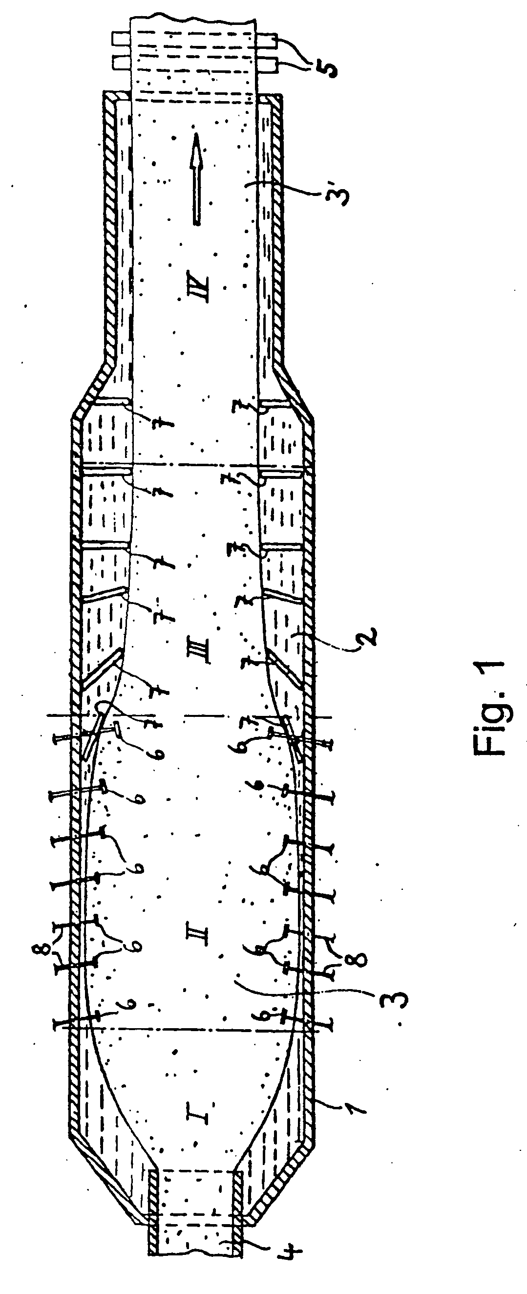
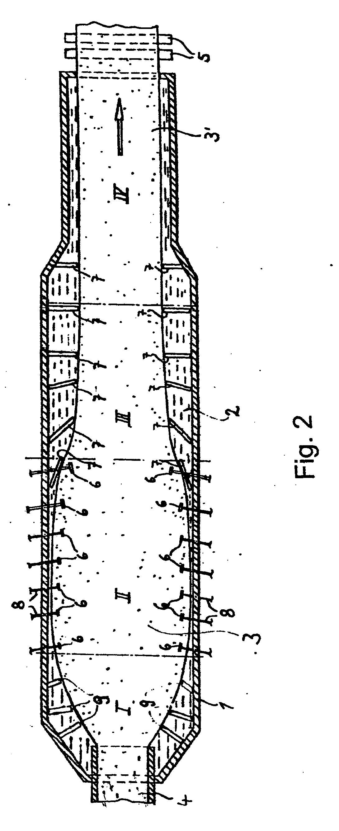
[0021] In the known float glass process for making flat glass a melt is poured onto a molten metal bath and the liquid glass spreads on the metal melt, thus forming a hot spread region. The spreading of the glass is subsequently assisted by so-called top rollers, which engage at the edge of the glass sheet and draw the glass sheet out further. A final outlet speed is imparted to the glass sheet by acceleration in the flow direction of the glass sheet behind the top rollers, which takes the molten metal downstream under the glass sheet and leads to a colder return flow in the upstream direction. The part of the return flow formed beside the glass sheet in the drawing region in the free surface (an additional part of the return flow occurs in the deeper layers of the bath) is prevented or hindered by placing barriers (flags) in the side surfaces of the tin bath in this region.
[0022] It was surprisingly found that the placement of flags in a region of the float bath, in which no return flow exists at the surface and in which the flags should have scarcely any effect according to the conventional understanding, still clearly reduce the thickness variations in the product float glass. This region of the float bath is the hot spread region, also the region, in which the glass freely spreads further under the influence of gravity. It is located upstream of the top rollers in the flow direction of the glass sheet. The glass has a viscosity of less than 106 dPas, especially a viscosity of 104 to 106 dPas, in this region.

Problems solved by technology

Although float glass is excellently suited for display applications because of its fire polished surface, it has not been possible to make display glass with thickness variations of less than 50 μm according to the float process with the currently required large substrate format with edge lengths of above 1800 mm.
Temperature non-uniformities, which are transferred to the hot forming glass sheet and lead to viscosity non-uniformities, arise because of the mixing of these flows.
These viscosity changes can then lead to undesired thickness fluctuations and waviness in the glass sheet.
In spite of the improvements in the flat glass manufacturing process up to now it has not been possible to make large-area thin flat glass substrates with a thickness of less than 1.5 mm, which met high quality specifications.

Method used


Image

  • Float glass process for making thin flat glass and thin flat glass substrate made with same
  • Float glass process for making thin flat glass and thin flat glass substrate made with same
  • Float glass process for making thin flat glass and thin flat glass substrate made with same

Examples


example

[0039] A thin flat glass sheet with a thickness of about 0.7 mm was drawn in a conventional float plant according to the prior art. The thickness of the glass sheet leaving the float plant of the prior art was measured. This thickness is shown graphically in FIG. 4. The measurement occurred by a double reflection method, in which a laser contour line is projected on the glass sheet and the thickness is calculated from the spacing of the received reflections from the front side and the rear side of the glass sheet respectively. The thickness variation is shown in FIG. 4. Then a flag was inserted in the molten metal on both sides of the forming glass sheet with a spacing of about 3.5 m from the front side of the float bath (bath inlet) in each case. The angle of the flag to the lateral wall amounted to 90°, the spacing to the sidewall 0 cm and the spacing to the glass flow 20 cm. The flag had a height of 70 cm and rests on the float tank bottom. The thickness fluctuation attained acco...


PUM

PropertyMeasurementUnit
Lengthaaaaaaaaaa
Fractionaaaaaaaaaa
Thicknessaaaaaaaaaa

Abstract

The thin flat glass substrate, especially for display engineering, has a thickness of less than 1.5 mm, a length of at least 1800 mm, a width of at least 1800 mm and a difference between a smallest thickness and largest thickness of less than 50 μm. The float glass process for making the improved flat glass substrate provides flags (9) in the molten metal bath in the hot-spread region on both sides of the forming glass sheet, to minimize the variation in thickness of the thin flat glass substrate formed by the process.

Description

BACKGROUND OF THE INVENTION [0001] 1. The Field of the Invention [0002] The present invention relates to a thin flat glass substrate with a thickness of less than 1.5 mm and to a method for manufacturing this sort of thin flat glass substrate. [0003] 2. Related Art [0004] Thin flat glass substrates are, among other things, used to make flat display screens, e.g. plasma display panels (PDP), field emission displays (FED), TFT liquid crystal display screens (TFT=thin film transistor), STN-liquid crystal display screens (STN=Super twisted nematic), PALC display screens (PALC=Plasma assisted liquid crystal), EL displays (EL electroluminescent) and the like. [0005] In flat display screens either a thin layer of liquid crystal compound is placed between two glass panels or respective dielectric layers are applied to the front and rear side of the rear and / or front glass panels, from which cells are formed, in which a phosphor is placed, according to the type of display. [0006] It is impor...

Claims


Application Information

Patent Timeline
IPC IPC(8): B32B17/06
CPCY10T428/24355C03B18/06C03B18/02C03B18/18
Inventor LANGSDORF, ANDREASLANGE, ULRICHVOGL, ARMINMORSTEIN, ANDREASROTERS, ANDREAS
Owner SCHOTT AG
Learn More