Control device for variable speed electric motors, particularly for power tools

a technology of electric motors and control devices, which is applied in the direction of control systems, dc motor speed/torque control, electric motor speed/torque regulation, etc., can solve the problems of deterioration of electrical contacts, friction between two parts, and wear of electrical contacts, so as to reduce the quantity of light transmitted, easy to compensate, and low dust sensitivity

Inactive Publication Date: 2006-06-01
POSITEC GROUP
View PDF4 Cites 20 Cited by
  • Summary
  • Abstract
  • Description
  • Claims
  • Application Information

AI Technical Summary

Benefits of technology

[0037] In addition to the main peculiar aspect of avoiding any movable mechanical contact, the control device according to the present invention achieves the following technical advantages: the device is wear-free, has an extremely long life (over 100,000 hours) of the light emitter, which exceeds by far the life of the power tool itself, is insensitive to moisture, vibrations and thermal variations. Moreover the device exhibits very low sensitivity to dust—which in the worst case could only decrease the quantity of the light transmitted, a minor inconvenience that does not prejudice the functionality and is easily compensated by a slight increase of the pressure on the trigger switch
[0038] Moreover, the control device according to the present invention achieves the following ergonomic advantages: the interface between the operator and the machine is improved, the shield can be shaped so that it realises a speed variation curve that is convenient to the operator, for a very accurate a precise operation of the speed control, the size of the trigger switch device is substantially reduced, so that is can be housed inside ergonomically convenient grip handles.
[0039] The present control device has also a limited cost impact on the finished product, said cost being largely compensated by the advantages in terms of life of the overall apparatus.

Problems solved by technology

Though widely emplyed in the industry, such trigger switch devices present several drawbacks.
Such a load increases the friction between the two parts and therefore make them to get worn with the usage.
Dust and moisture deteriorate the electrical contacts between the wiping parts and the resistive track.
Specifically, small particles of dust increase the friction and therefore favour the wear process.
Vibrations—which are typical of all kinds of power tools and similar apparatuses—can cause micro-gaps of the resistive tracks, therefore affecting the functionality of the device.
Ultimately, the effect of the above-mentioned problems is that of providing a poor interface with the operator, since the speed variation cannot be conveniently controlled by the operator through the time.
A further wearing causes gaps so that the motor is not powered in certain positions of the trigger.
As a matter of facts, it is widely statistically proven that the first cause of failure in power tools is due to the trigger switch device.
Specifically, according to industry return figures, around 70% of the defect rate of power tools is due to failures of trigger switch devices.
With the existing technology, conventional trigger devices as described above cannot be small enough to allow such an ideal size of the grip.
The inconvenient is even worsened by the fact that the number of women using power tools is rapidly increasing.
Due to the above mentioned size limitation, a grip handle for matching the substantially smaller female hand size cannot be presently realized.
However, these known optical devices cannot be readily implemented into hand-held power tools insofar as the light emitters used therein make use of bulb lumps and / or neon lamps.
The main limitations associated with bulb lamps are their too large size in comparison with a relatively small grip handle, the excessive heat generation, the high sensitiveness to vibrations, the shorter life than conventional wiping contacts which brings about frequent replacements, which replacements are difficult to perform due to the location of the trigger switch inside the power tool.
The main limitations associated with the use of neon lamps are the too large size, sensitiveness to vibrations, limited light spectrum and consequent limited ability to properly drive the receiver.
However, up to now the availability of these devices has been limited to single-colour LEDs (e.g. red, green, yellow) whose limited spectrum cannot conveniently drive the receiver unless using several LEDs to increase light concentration.
Of course, the use of a plurality of LEDs would have a heavy impact on the size of the trigger switch.
A further disadvantage deriving from this solution is associated with the power supply circuit.
In fact, LEDs are operating at low voltage (approx 2V) and therefore require a power transformer to consistently reduce the mains power (110 / 230V), and such a transformer cannot be easily housed into a hand-held power tool due to its size limitation.
A further method for powering LEDs is that of using a resistor voltage divider, but this solution involves a large heat dissipation, thus resulting in excessive waste of energy.
Moreover, the adoption of a plurality of LEDs would generate a wide light beam that would require the use of a large shield which cannot be conveniently housed into a limited space.

Method used


Image

  • Control device for variable speed electric motors, particularly for power tools
  • Control device for variable speed electric motors, particularly for power tools
  • Control device for variable speed electric motors, particularly for power tools

Examples


Embodiment Construction

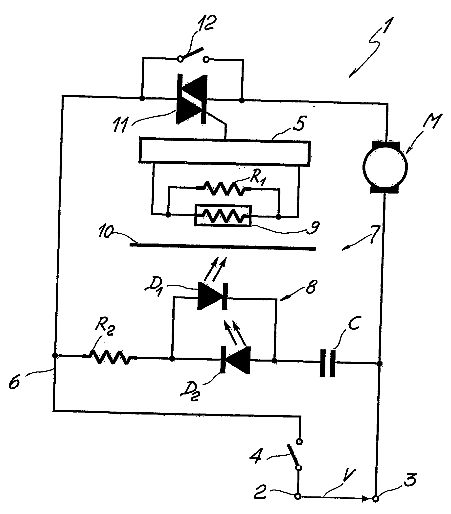
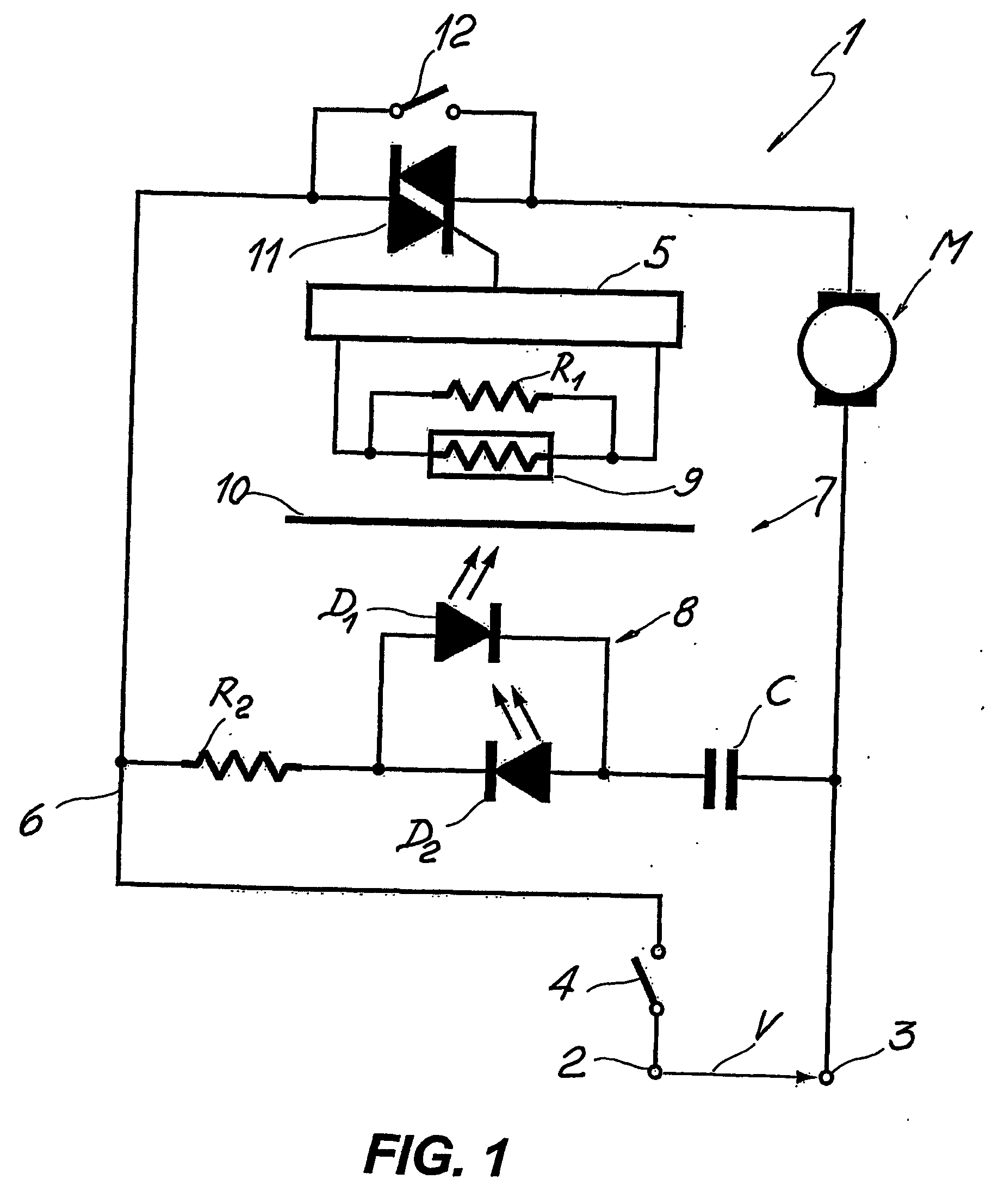
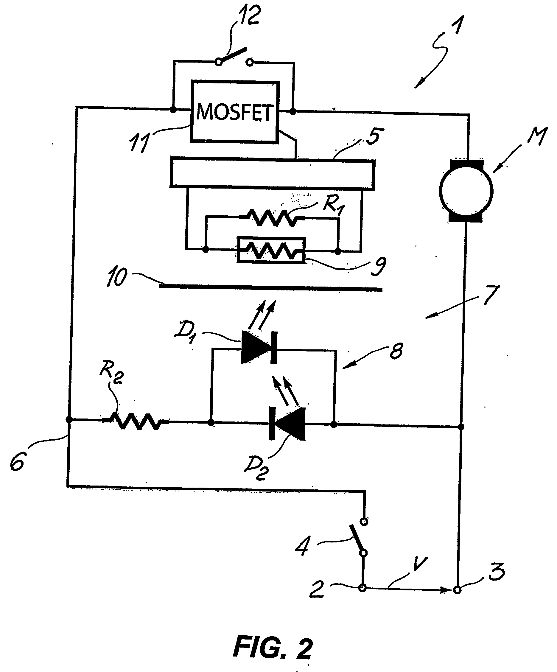
[0043] With reference to the above referenced drawings, a speed control device for varying and controlling the speed or other operating parameter of a motor M is overall designated with the reference numeral 1.

[0044] Motor M may be any AC or DC motor and is advantageously mounted to any hand held power tool or other small size or miniaturised electrically powered apparatus.

[0045] In the embodiment shown in FIG. 1, motor M is of the AC type and is connected to the terminals 2, 3 of an electric power source V by means of the speed control device 1. The electric power source V is usually equal to the power supply voltage, namely 230V in Europe and 115V in North America.

[0046] Optionally, a power switch 4 may be serially connected to the terminal 2 of the electric power source V to selectively switch current to the speed control device 1 and to the motor M.

[0047] The electric power applied to the motor M is controlled by means of an electronic driver unit 5 serially connected along ...


PUM


Abstract

A device for controlling variable speed electric motors, particularly for hand held power tools and other miniaturised electrically powered apparatuses, comprises an electronic driver unit (5) connectable to the terminals (2, 3) of an electric power source for supplying electric current to at least one electric motor (M) and an optical switch device (7) for triggering the electronic driver unit (5). The optical switch device (7) comprises light emitting means (8) and light transducer means (9) for detecting and converting light into an electric variable signal. The light transducer means (9) are operatively connected to the electronic driver unit (5) for controlling the electric motor (M). The light emitter means (8) comprise at least one white light, high brightness LED (D1, D2) connected in parallel to the electric power line terminals (2, 3) by means of a miniaturised power circuit. The miniaturised power circuit comprises at least one resistor (R2) when said at least one electric motor (M) is a DC motor, and a capacitive phase displacement power supply (C, R2) when said electric motor is an AC motor. The capacitive phase displacement power supply (C, R2) comprises at least one capacitor (C) and an input resistor (R2) adapted to supply said diodes (D1, D2) with a threshold voltage.

Description

TECHNICAL FIELD [0001] The present invention relates to a control device for controlling variable speed electric motors. More specifically, the control device of the present invention finds application in the field of the hand held power tools such as e.g. drills, hammer drills, circular, reciprocating and jig saws, routers, planers, sanders, grinders, etc, an other small sized and miniaturised electrically powered apparatuses. BACKGROUND ART [0002] Trigger operated control devices are normally housed in the grip handle of power tools in such a manner that they can be operated with the pressure of one or more fingers of the same operator's hand that is holding the tool. Such control devices are used for operating the power tools by means of switching on the motor and adjusting the speed from 0 up to the maximum speed. [0003] The above-mentioned control devices generally comprise each a main mechanical switch to connect the main power to an electronic control circuit, a variable resi...

Claims


Application Information

Patent Timeline
Patent Type & Authority Applications(United States)
IPC IPC(8): H02P5/00H02P7/28H02P27/02
CPCH02P7/28H02P27/02
Inventor ANDRIOLO, PAOLO
Owner POSITEC GROUP
Why Eureka
Try Eureka