Fabrication of waveguides and bragg gratings with uv-irradiation

a technology of bragg grating and waveguide, which is applied in the direction of glass making apparatus, instruments, optics, etc., can solve the problems of poor grating quality, difficult and costly devices to produce, and inability to realise and optimise both the waveguide core and the bragg grating superstructure of the channel, so as to enhance the photosensitivity, the complexity of the device that can be fabricated is further increased, and the sample is highly accurate repositioning

Inactive Publication Date: 2006-06-15
UNIV OF SOUTHAMPTON
View PDF8 Cites 35 Cited by
  • Summary
  • Abstract
  • Description
  • Claims
  • Application Information

AI Technical Summary

Benefits of technology

[0033] The method may further comprise repeating the positioning of the spot and the causing of relative movement so as to define one or more additional channels with paths substantially the same as the path of the said channel. This feature allows gratings and/or uniform waveguides to be written over previous structures, so that the complexity of the devices that can be fabricated is further increased. Use of computer control enhances this feature, because highly accurate repositioning of the sample can be achieved.
[0034] The photosensitive region may be loaded with hydrogen and/or deuterium to enhance the photosensitivity. The hydrogen and/or deu

Problems solved by technology

However, it has been found difficult to realise and optimise both the channel waveguiding core and the Bragg grating superstructure when defined in the same host substrate material.
However, the resulting devices are difficult and costly to produce.
Also, the grating quality has been found to be poor and the spectral response of the grating is difficult to tailor, so applications of the resulting device

Method used


Image

  • Fabrication of waveguides and bragg gratings with uv-irradiation
  • Fabrication of waveguides and bragg gratings with uv-irradiation
  • Fabrication of waveguides and bragg gratings with uv-irradiation

Examples


first embodiment

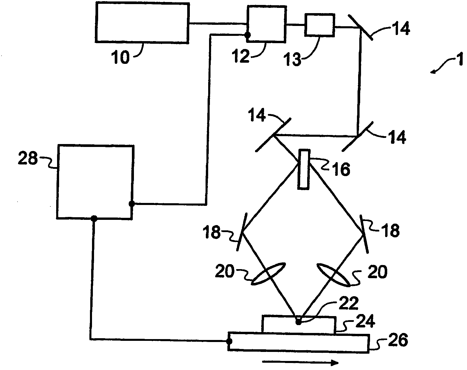
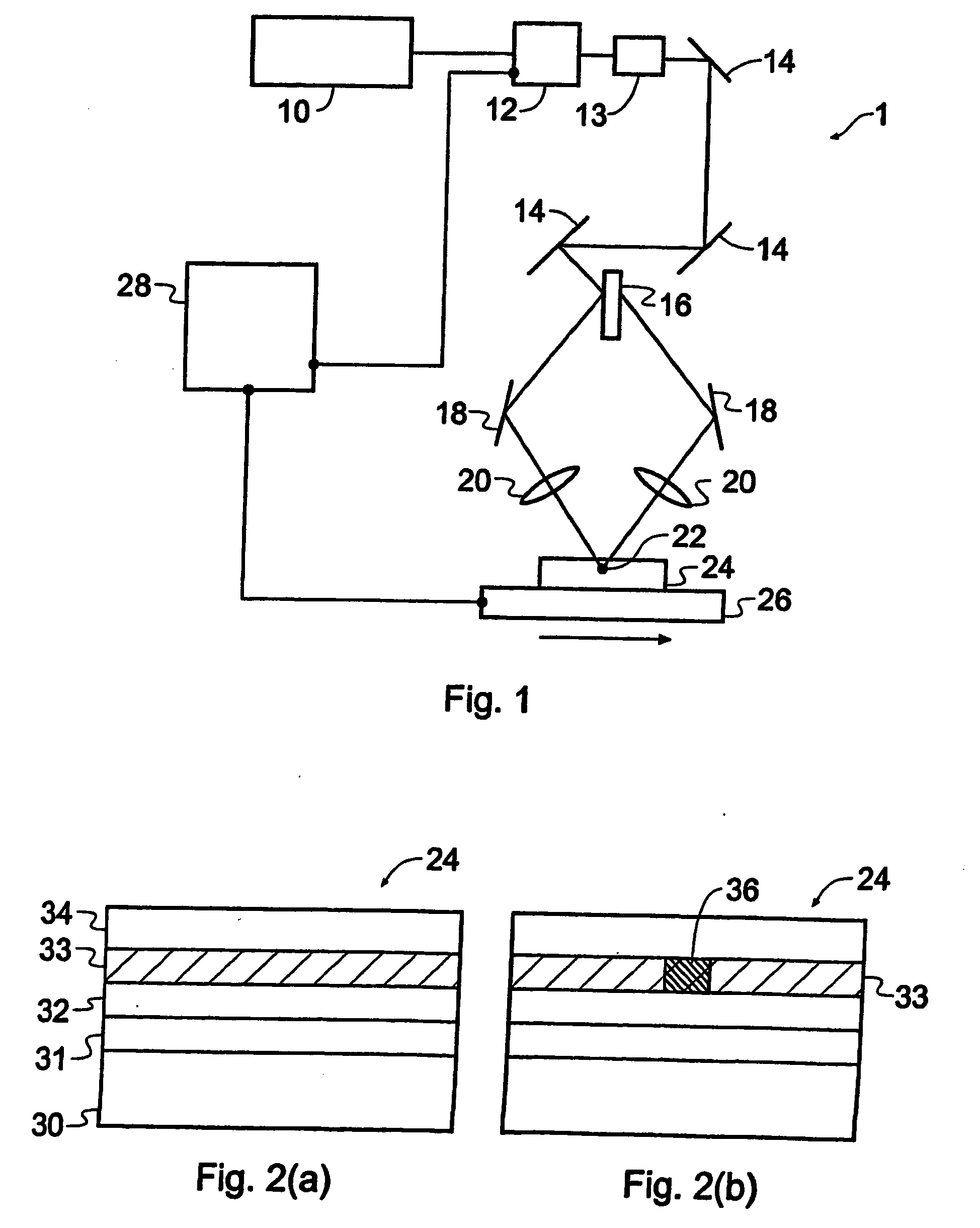
[0057]FIG. 1 shows a schematic depiction of apparatus 1 suitable for carrying out methods according to embodiments of the present invention. The apparatus comprises a laser system 10 operable to generate ultraviolet light, for example a continuous wave argon-ion laser with a frequency-doubled output at 244 nm. The output beam of the laser system 10 passes through an acousto-optic modulator 12, operable to modulate or strobe the beam so as to form pulses of light. A spatial filter 13 is positioned after the modulator to improve beam quality. The beam is then steered using a series of mirrors 14 to a beam splitter 16, which splits the beam into two equal parts, each following its own path. Further, independently movable, mirrors 18 redirect the two parts of the beam through focussing lenses 20 so that the parts overlap at an intersection, and interfere to form an interference pattern comprising a spot of light 22 having a periodic series of bright and dark intensity fringes. The perio...


PUM

PropertyMeasurementUnit
Angleaaaaaaaaaa
Photosensitivityaaaaaaaaaa
Refractive indexaaaaaaaaaa

Abstract

A method of simultaneously defining a waveguide and grating in a sample of photosensitive material comprises providing a sample of material (24) having a region which is photosensitive to light of a specific wavelength, generating a spot of light (22) at the specific wavelength, the spot having a periodic intensity pattern of high and low intensity fringes, and a width which is related to the width of the channel, positioning the spot within the photosensitive region and causing relative movement between the sample and the light spot along the desired path of the waveguide/grating define a channel of altered refractive index by exposing parts of the photosensitive region to the light spot. Modulation of the light spot to produce multiple exposures produces a grating, while continuous exposure results in a uniform waveguide. These structures can be written in straight lines or around curves, and can be accurately overwritten, so that complex optical devices can be produced in a single fabrication step.

Description

BACKGROUND OF THE INVENTION [0001] The present invention relates to the fabrication of waveguide structures containing Bragg gratings. [0002] Optical fibres have an optical waveguiding function defined by a high refractive index core surrounded by a lower refractive index cladding. Further functionality is available by writing grating structures, known as Bragg gratings, into the core. These structures comprise a series of grating planes of alternating high and low refractive index, and give a spectral reflection / transmission response which depends on the periodicity of the grating planes. These gratings can be used to create a wide range of fibre-based optical devices for applications including dispersion compensation, optical feedback and wavelength multiplexing. [0003] Conventionally, fibre Bragg gratings are fabricated by exposing fibre to ultraviolet (UV) light so as to induce a refractive index modification in photosensitive material in the fibre core. This technique is depend...

Claims


Application Information

Patent Timeline
IPC IPC(8): G02B6/34G02B6/12G02B6/124G02B6/13
CPCG02B6/02152G02B6/12007G02B6/124G02B6/13
Inventor SMITH, PETER GEORGE ROBINWILLIAMS, RICHARD BIRDALBANIS, VASSILIOSGAWITH, CORIN BARRY EDMUNDWATTS, SAMUEL PAULEMMERSON, GREGORY DANIEL
Owner UNIV OF SOUTHAMPTON
Why Eureka
Try Eureka