Nanoparticle coated nanostructured surfaces for detection, catalysis and device applications

a nanostructured surface and nanoparticle technology, applied in the field of nanoparticles and nanostructures, can solve the problems of insufficient sensitivity of surface raman scattering, inability to generate a strong restoring force, and large fluorescence bands that are relatively insensitive to molecular structure, etc., and achieve enhanced surface raman scattering and strong surface plasmon optical absorption

Inactive Publication Date: 2006-06-29
PENN STATE RES FOUND
View PDF8 Cites 68 Cited by
  • Summary
  • Abstract
  • Description
  • Claims
  • Application Information

AI Technical Summary

Benefits of technology

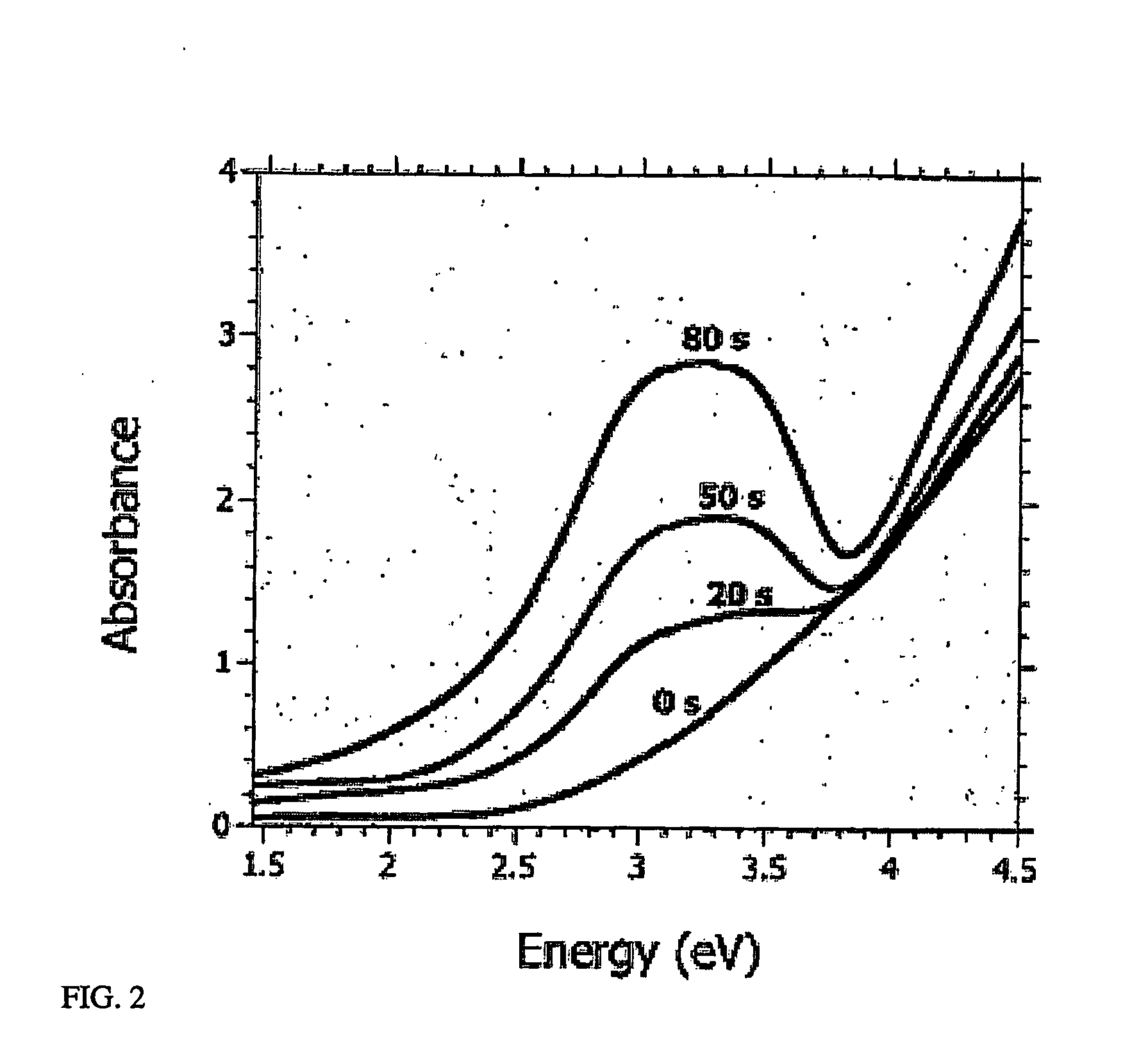
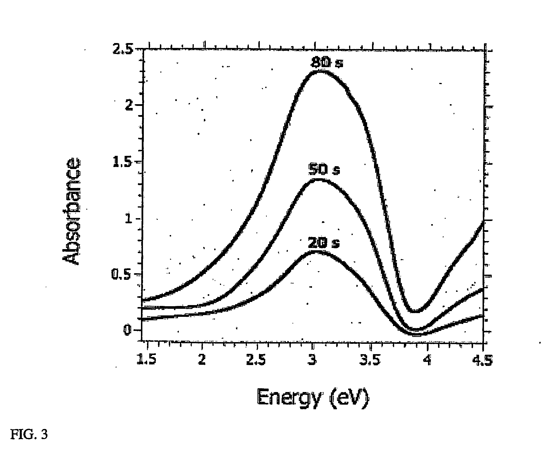
[0017] A non-vacuum-based, non-collodial chemistry-based method of synthesizing metal nanoparticles and a nanoparticle-nanostructured material composite obtained by that method are disclosed hereinbelow. Applying the methods of this invention, nanoparticles of certain metals, such as but not limited to Au, Ag, Cu, Pd, and Pt, their alloys and compounds, can be controllably synthesized on the surfaces of nanostructured, porous void-column films by exposure of this material to the salt solutions of these metals. These composite nanoparticle / void-column film substrates have been found to yield strong surface plasmon optical absorption and surface enhanced Raman scattering (SERS). Since the method of this invention does not require any reducing agents, coating agents, or catalysts to form the metal nanoparticles, it is very attractive. These particles may be immobilized on the nanostructured material or the material may be used to generate the particles for injection into some fluid flow environment. The metal nanoparticles can be coating-free, immobilized, and disbursed on a surface. the surface may involve anti-reflection systems and reflection coatings for further optical enhancement. The metal nanoparticle creation reaction of this invention is attributed to galvanic displacement, where the film surface itself serves as the reducing agent and electron source for reduction of the metal bearing medium; e.g, a metal salt. In the present invention no HF etching or oxide removal is necessary for nanoparticle forming to occur and, also, no metal coating (catalyst) is needed.

Problems solved by technology

When the particle size increases (or when nanoparticles aggregate so electrons can travel from one nanoparticle to another) electrons become dephased and they cannot generate a strong restoring force.
However, the broad fluorescence bands are relatively insensitive to molecular structure.
The use of Raman scattering to investigate adsorbates on surfaces was initially thought to be of insufficient sensitivity due to the extremely small cross sections associated with this effect (−10−30 cm2 per molecule which is 14 orders of magnitude smaller than that of a fluorescent dye molecule in fluorescence).
Furthermore, if colloidal particles are desired to be disposed and immobilized on a substrate, it is difficult to obtain nanoparticle arrays at desired uniformity, density, and dispersion by using colloidal nanoparticles.
However, this approach of synthesizing metal nanoparticles on a flat surface offers no control over particle size, spacing and dispersion.
(See L. Gunarsson, E. J. Bjerneld, H. Xu, S. Petronis, B. Kasemo, and M. Käll, Appl. Phys. Lett. 78, 802 (2001)) However, this technique involves high costs, low throughput and is limited to a minimum particle size of −10 nm.
18, 633 (1981)) Although vapor deposition is a lower cost and higher throughput process than electron beam lithography, control of particle size and spacing is difficult.

Method used


Image

  • Nanoparticle coated nanostructured surfaces for detection, catalysis and device applications
  • Nanoparticle coated nanostructured surfaces for detection, catalysis and device applications
  • Nanoparticle coated nanostructured surfaces for detection, catalysis and device applications

Examples


Embodiment Construction

[0035] A non-vacuum-based, non-collodial chemistry-based method of synthesizing metal nanoparticles and nanoparticle-nanostructured material composites obtained by that method are disclosed hereinbelow.

[0036] In an embodiment of the method of this invention for synthesizing macro, micro or nanoscale nanoparticles, a fluid stream, carrying a precursor solution is directed over the nanostructured / nanotextured material initiating a nanoparticle synthesis and entraining the nanoparticles in the flow. A fluid stream may be created in a macro, micro or nanoscale fluidics system by either electrokinetic or hydrodynamic pumping. A fluid stream is relative motion of a fluid with respect to the nanostructured material. In one embodiment, but not limited to, a salt solution is stirred in a beaker and the nanostructured material is placed (“dipped”). When the nanostructured material is at rest with respect to the beaker, the nanostructured material will be in a flow stream. The Particle precur...


PUM

PropertyMeasurementUnit
roughnessaaaaaaaaaa
pore sizeaaaaaaaaaa
sizeaaaaaaaaaa

Abstract

A non-vacuum-based, non-collodial chemistry-based method of synthesizing metal nanoparticles and nanoparticle-nanostructured material composites obtained by that method. An embodiment of the method of this invention for fabricating a nanoparticle-nanostructured material composite and synthesizing nanoparticles includes preparing a nanostructured/nanotextured material, and, contacting the nanostructured/nanotextured material with a solution. Nanoparticles are synthesized on the nanostructured/nanotextured material as a result of the contact. The method of the present invention can be utilized to fabricate SPR and SERS substrates for sensing and detection. Additional systems based on this approach (e.g., surface plasmon resonance absorption and alloying sensors and nanocatalysts) are described.

Description

BACKGROUND OF THE INVENTION [0001] This invention relates generally to nanoparticles and nanostructures and specifically to a method for coating nanoparticles on nanostrustured surfaces and systems and devices fabricated by the method of this invention. [0002] Metal (e.g., Ag, Au and Cu) nanoparticles can exhibit a strong optical absorption and reflectance in the UV-visible range of the electromagnetic spectrum that is not present in the spectrum of the bulk metal. When the particle size is much smaller than the wavelength of the incident electromagnetic radiation, the electrons in the particle can move in phase which can result in their generating a giant oscillating dipole (or multipole depending on the shape of the particle). This collective motion of the electrons generates surface polarization charges on each side of the particle, which act as a restoring force on these electrons. Because of the restoring force a resonance condition occurs at a certain frequency at which the am...

Claims


Application Information

Patent Timeline
Patent Type & Authority Applications(United States)
IPC IPC(8): B32B13/04B01J35/10B05B7/00B82BC23C16/00H01B1/00H05H1/26
CPCB01J35/006Y10T428/24926B82Y15/00B82Y20/00B82Y25/00B82Y30/00G11B5/706G11B7/241Y10S977/778Y10S977/723Y10S977/707Y10S977/784Y10S977/764H01F1/0054B01J35/10
Inventor KALKAN, ALI KAANFONASH, STEPHEN J.
Owner PENN STATE RES FOUND
Why Eureka
Try Eureka