
Externally activated neuro-implant which directly transmits therapeutic signals

Inactive Publication Date: 2006-06-29
TULGAR METIN
View PDF9 Cites 216 Cited by
  • Summary
  • Abstract
  • Description
  • Claims
  • Application Information

AI Technical Summary

Benefits of technology

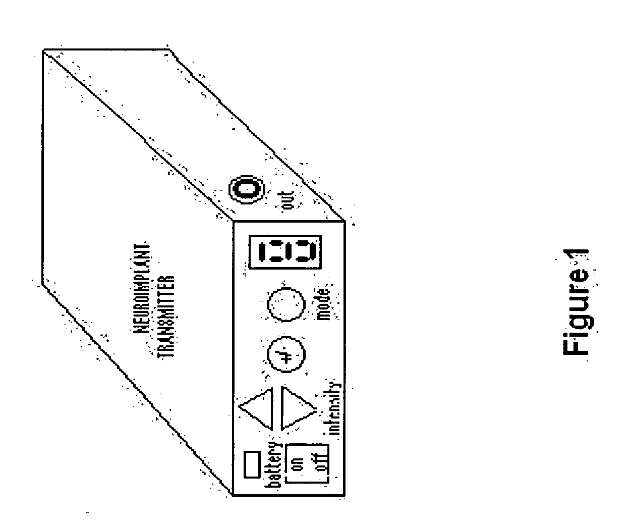
[0010] The system mainly consists of four elements: two coils, one passive coil and one active coil, an electrode and a transmitter. The passive coil and electrode are internal components implanted in the body; the active coil and transmitter are external. The passive coil is connected to the electrode via insulated thin wires. The active coil is then placed on the skin overlying the implanted passive coil. Therapeutic signals produced by the transmitter are linked to the active coil by means of a flexible cable, and are transmitted through the coils by inductive coupling across the skin of the patient. Each coil is housed in a ferrite pot core that enhances inductive coupling, and minimizes the size of coils thus facilitating the construction of a passive coils array to use multi-contact electrodes for effectively selecting the target neurons.
[0011] The main goal of the present invention is that the implanted part of the system is completely passive, having only a coil housed in a ferrite pot core, thus eliminating the risk of additional surgery due to electronic breakdown or battery replacement.
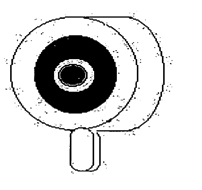
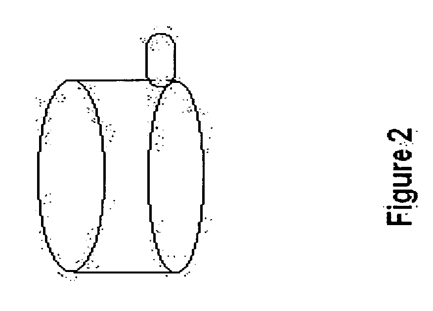
[0017] Housing each of the external (2) and internal coils (3) in a ferrite pot core [(4),(52),(65)] enhances inductive coupling and miniaturisation of the system. The external active coil [(2),(4),(52),(65)] is bigger in size (29 mm in diameter, 9 mm in height) to keep the coupling efficiency against lateral movements [(48),(49)] over the implanted passive coil (3) (FIGS. 3, 13 and 14). The internal coil [(3),(80),(88)] is small enough in size (14.4 mm in diameter, 7.5 mm in height) (FIGS. 2 and 12); two or three of them can be used together to form a passive coils array to enable the use of multi-contact electrodes (FIGS. 21, 24 and 27). The only thing the patient need to do is to move the single active coil (2) over the passive coils array [(83),(84)] to select the most effective channel of the multi-contact electrode for switching of electrical stimulation between a number of sites, and thereby combat some of the difficulties of placement, targeting and accommodation (FIG. 1).
[0019] The transmitter circuit of the present system (FIG. 5) has less number of electronic components (12),(13),(14),(15),(16),(17),(18),(19),(20),(21),(22),(23),(24),(25),(26),(27),(28),(29), (30),(31),(32),(33),(34),(35),(36),(37),(38),(39),(40),(41),(42)] than those of even common portable transcutaneous electrical nerve stimulator (TENS) devices. It is, therefore, a cheaper and more reliable device. On the other hand, it is a versatile system providing all form of electro-therapeutic signals including conventional stimulation (in this mode; continuous pulses are repeated at a constant frequency between 30 Hz and 100 Hz), the burst (in this mode; 80 ms long trains of pulses with an internal frequency of 80 Hz are repeated 1.3 times a second, each train consisting of 7 pulses) and frequency modulated stimulation patterns (in this mode; fast pulses (110 Hz) are slowed down (55 Hz) for a short period (90 ms) 1.3 times a second, and then they get faster again), that are known to be more effective in some clinical conditions, with externally easy programming (FIGS. 8, 9, 10 and 11).
[0020] The signal transmitted by the existing RF and totally implantable devices is monophasic (FIGS. 19 and 20) which means involment of direct current (DC). Electrolysis resulting from the polarity is a known factor to be considered. The pulse induced by the present system is biphasic DC free signal (FIGS. 16 and 17) which is useful to minimize any undesirable electrolysis phenomena that may result in breakage in the lead of electrode and tissue necrosis.
[0021] All these factors convey the additional advantages of safety and reliability while reducing the cost.

Problems solved by technology

In the case of persistent and extensive pain, transcutaneous stimulation is not adequate due to need for multiple electrode placement and increased skin impedance.
There are many reports about the successful use of neuroimplants which have been around for 38 years, but some complaints about their performance were also voiced.
3) Programming difficulties: patients wearing a fully implantable system have to go to hospital at certain times for the arrangement of stimulation parameters, and sometimes there are difficulties in externally programming the implanted circuit.
Some of the most sophisticated systems do allow variations of some parameters, but this facility is both limited and expensive.
5) Electrode position: during the operation the electrode may be misplaced or, following the operation, electrodes may migrate, thus reducing the efficacy of stimulation.
6) The expense of the equipment: the high cost of the present implants severely limits widespread use of this clinically approved method.
While the use of magnetic coupling principles in numerous electromagnetical devices (e.g. transformers), electromagnetic coils housed in a ferrite pot core have not previously been used in neuroimplantation and other implantable medical devices.
A big implant is not surgically preferrable.

Method used


Image

  • Externally activated neuro-implant which directly transmits therapeutic signals
  • Externally activated neuro-implant which directly transmits therapeutic signals
  • Externally activated neuro-implant which directly transmits therapeutic signals

Examples


Embodiment Construction

[0013] This invention relates to an externally powered and controlled signal transmission system [(1),(2),(3),(4),(5),(6),(7),(8),(9),(10),(11)] for implantable medical devices, particularly neuro-implants, e.g. spinal cord stimulator implant to control pain and to treat vascular diseases such as peripheral vascular disease in lower extremities and coronary arterial disease, angina pectoris and motor disorders, vagus nerve stimulator implant for the management of epilepsy, phrenic nerve stimulator implant for diaphramme pacing in respiratory disorders, deep brain stimulator implant for the management of parkinson's disease, peroneal nerve stimulator implant for gait correction of dropped foot in hemiplegy, cohlear implant for improving hearing (FIGS. 1 and 4).

[0014] The device is essentially two electromagnetic coils [(2),(3)]—a passive coil (3) and an active coil (2)—through which electrical signals for neurostimulation are transmitted by trans-dermal inductive coupling FIGS. 1 an...


PUM


Abstract

An externally powered and controlled neuro-implant system for transmission of stimulating therapeutic signals to an implantable electrode. The system basically consists of two coils, one external active coil and one internal passive coil each housed in a ferrite pot core which enhances inductive coupling and minimizes the coils in size, thus facilitating the construction of a passive coils array to enable the usage of multi-contact electrodes for swithching of the electrical stimulation between a number of sites along the target neurons. The implanted part of the system, comprising only a coil housed in a ferrite pot core, is fully passive. The passive coil, that is implanted under the skin, is connected with the electrode placed in neighbouring of the target neural tissue via implanted thin medical grade wires. The active coil is placed on the skin overlying the passive coil. Therapeutic signals produced by the transmitter outside the body are transmitted through the coils by inductive coupling across the skin of the patient.

Description

CROSS-REFERENCE TO RELATED APPLICATION [0001] This application is a National Stage entry of International Application No. PCT / TR2003 / 000092, filed Dec. 2, 2003, the entire specification claims and drawings of which are incorporated herewith by reference.BACKGROUND OF THE INVENTION [0002] The present invention relates to an externally activated signal transmission system for especially implantable neurostimulators. In the relevant medical literature, such devices are called neuro-implant. Neuro-implant is a device that electronically stimulates the nerves system. Neurostimulation is a process, by which nerves partially loosing their function as a result of disease or travma, are stimulated using artificial electrical pulses for regeneration. Electrical signals used for this purpose must be consistent with the natural activity of human neurophysiology. [0003] Implanted electrical stimulators were first used in 1967. They were primarily developed as a spinal cord stimulator for the man...

Claims


Application Information

Patent Timeline
IPC IPC(8): A61N1/40A61N1/34A61N1/08A61N1/36A61N1/372
CPCA61N1/08A61N1/36021A61N1/37223A61N1/36017A61N1/37252A61N1/36062A61N1/36128
Inventor TULGAR, METIN
Owner TULGAR METIN
Learn More