Apparatus and process for mediated electrochemical oxidation of materials

a technology of electrochemical oxidation and apparatus, which is applied in the direction of sludge treatment by oxidation, water treatment parameter control, disinfection, etc., can solve the problem that the dumping of materials in landfills is a considerable risk for the users of these materials

Inactive Publication Date: 2006-07-06
SCIMIST LNC
View PDF20 Cites 94 Cited by
  • Summary
  • Abstract
  • Description
  • Claims
  • Application Information

AI Technical Summary

Benefits of technology

[0043] In the case of certain electrolyte compositions, an AC voltage is impressed upon the DC voltage across the electrodes in the electrochemical cell, or the AC voltage may be applied between the electrodes without the presence of a DC voltage. The AC voltage is used to retard or prevent the formation of surface films on the electrodes that would have a performance limiting effect within the voltage range of interest (i.e., approximately 2.5 to 3.5 volts).

Problems solved by technology

The dumping in landfills has considerable risk for the users of these materials.

Method used


Image

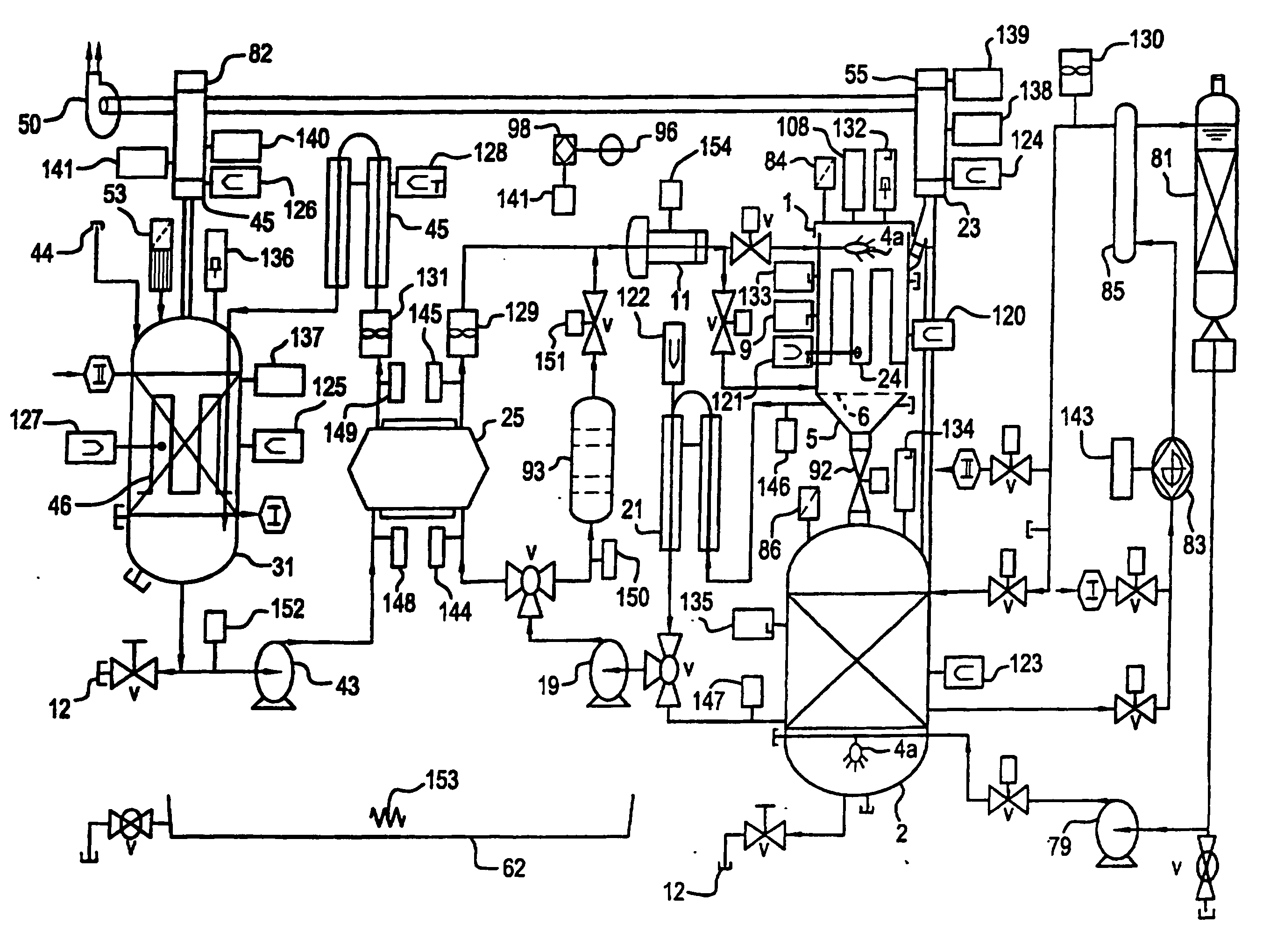
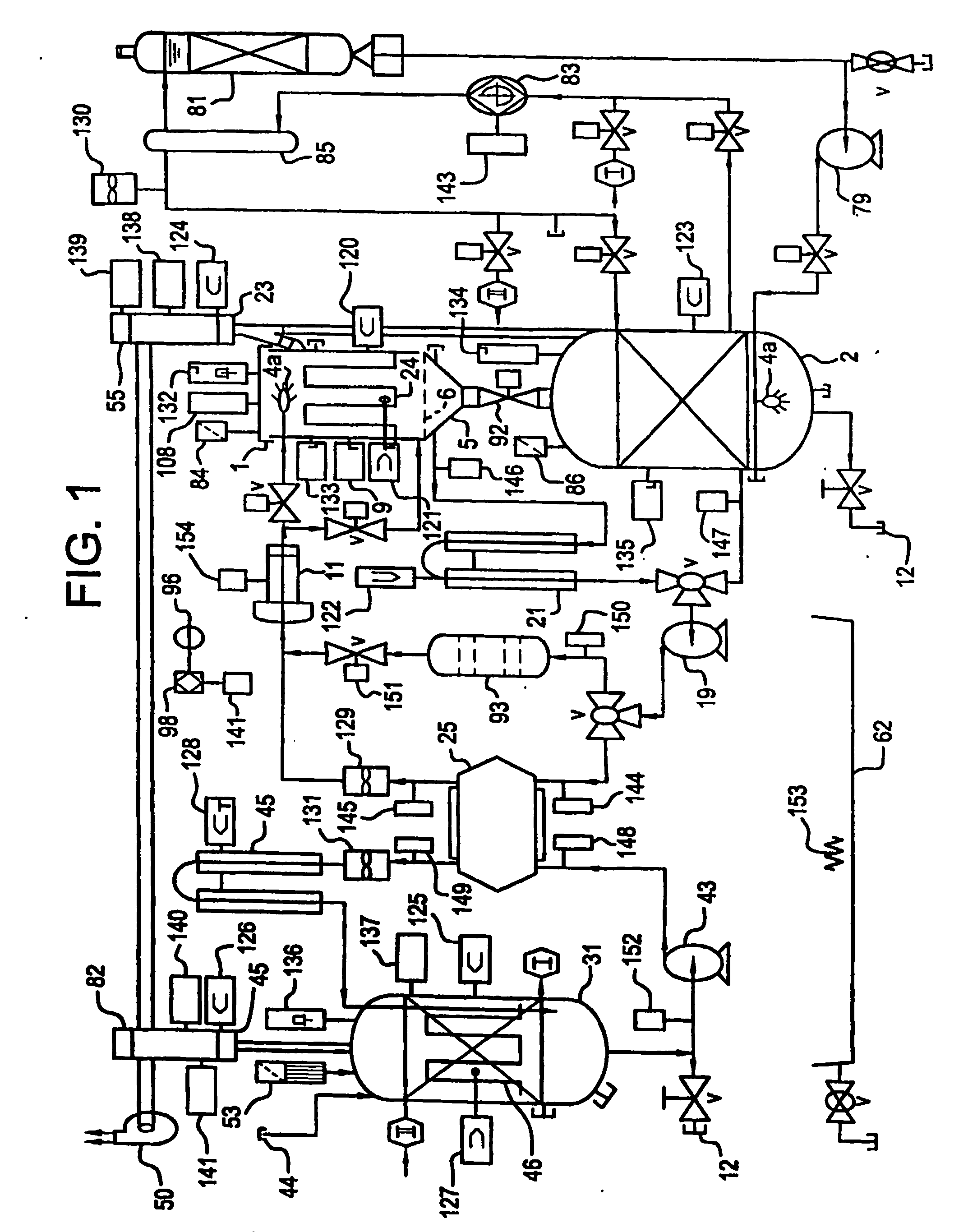
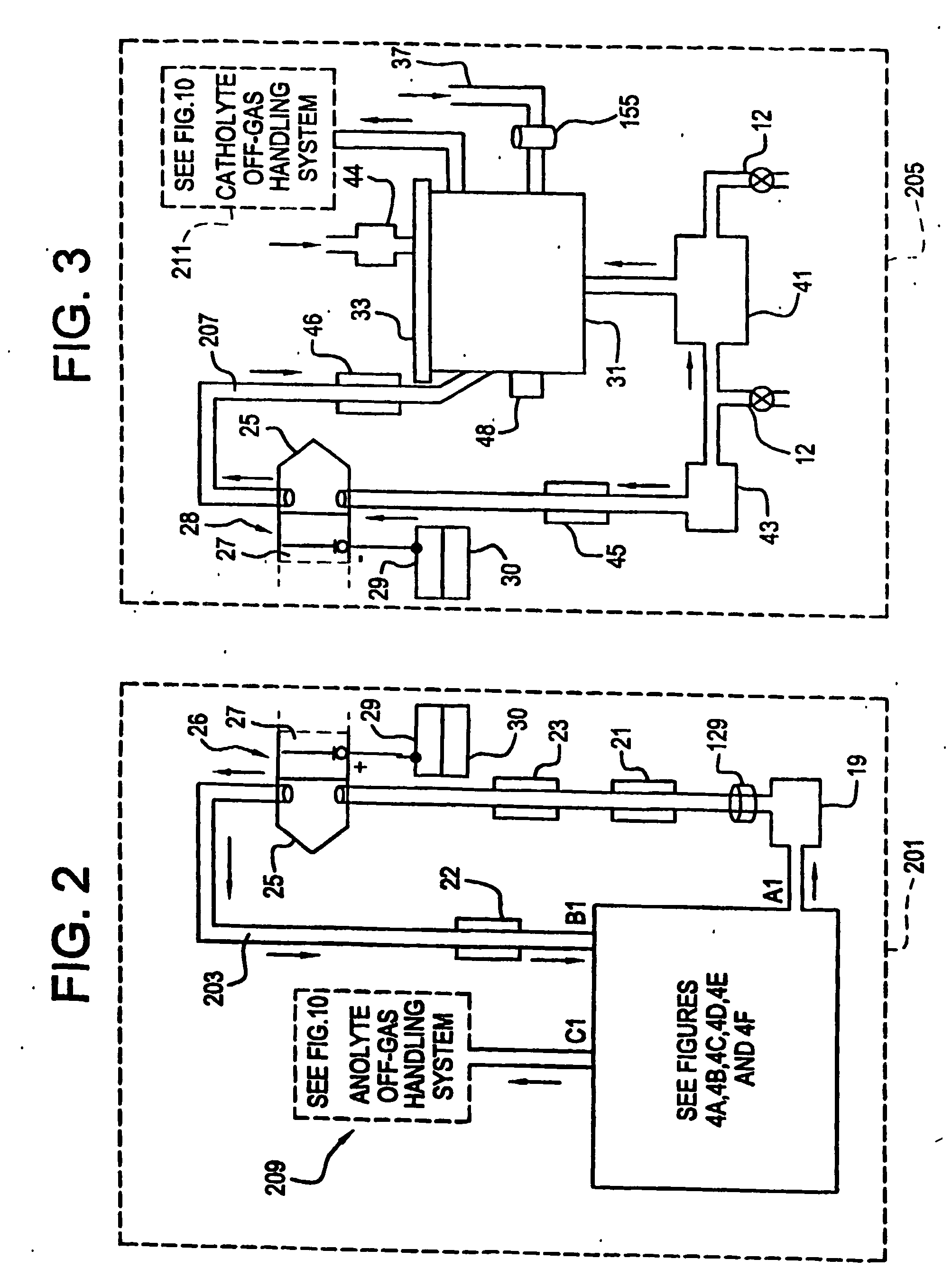
  • Apparatus and process for mediated electrochemical oxidation of materials
  • Apparatus and process for mediated electrochemical oxidation of materials
  • Apparatus and process for mediated electrochemical oxidation of materials

Examples


first embodiment

[0164] an electrochemical cell 25a is a ceramic box 270 and lid 271 styles, shown in FIG. 6A. Anolyte solution 203 enters the electrochemical cell 25a through the lid 271 by tubing 274, from the pump 19 and exits through tubing 276. Catholyte solution 207 enters the electrochemical cell 25a through input tubing 278 from pump 43 and exits through output tubing 280 in the lid. The entrance and exiting through the lid eliminates the source of leakage in the current designs. The box 270 is made of a molded ceramic as a unibody construction which is significantly less expensive to construct than the current state-of-the-art. The lid 271 is clamped to the box using nuts and bolts with the bolts passing through clamp holes 60. The lid 271 includes a gasket 272 thereby creating a liquid tight seal. The ease of access to the interior of the electrochemical cell 25a significantly improves the maintenance of the electrochemical cell 25a. The inside surfaces of the ceramic box 270 and the lid 2...

second embodiment

[0165] this electrochemical cell 25a bonds oxidation resistant ion selective membranes 27a (e.g., Nafion™) over the interior walls that are serving as the ceramic membranes 27a The addition of these membranes 27a supplements the performance of these ceramic membranes 27a.

third embodiment

[0166] A third embodiment uses a second electrochemical cell 25b, FIG. 6B, which has a pier box 270a and lid 284. The materials used for the FIG. 6B embodiment are selected from the following list of materials: fiberglass, polypropylene, metals and composite metals. The interior surfaces of this design will have PTFE coating to protect these surfaces from the oxidizer in the anolyte solution 203 and the acids or alkaline in the catholyte solution 207. The anodes 26 and cathodes 28 slide into electrode slots 56 in the electrochemical cell 25b walls with the electrical connection to them coming through the lid 284 to an anode bus 52 and cathode bus 54. The membrane 27 is held by membrane frame 58. The walls of the box have ridges 277 and grooves 279 (shown in FIG. 6A) made into them to promote turbulent flow thereby reducing adverse boundary layer related phenomena at the anodes 26. In another embodiment of this configuration the box 270a and lid 284 are composed of metal(s) and or me...


PUM

PropertyMeasurementUnit
boiling pointaaaaaaaaaa
pressureaaaaaaaaaa

Abstract

A unique apparatus unique apparatus and process that uses mediated electrochemical oxidation (MEO) for: (1) Destruction of: a) nearly all organic solid, liquid, and gases materials, except fluorinated hydrocarbons; b) all biological solid, liquid, and gases materials; c) and/or dissolution and decontamination (such as cleaning equipment and containers, etc.) of nearly all inorganic solid, liquid, or gas where higher oxidation states exist which includes, but is not limited to, halogenated inorganic compounds (except fluorinated), inorganic pesticides and herbicides, inorganic fertilizers, carbon residues, inorganic carbon compounds, mineral formations, mining tailings, inorganic salts, metals and metal compounds, etc.); and d) combined materials (e.g. a mixture of any of the foregoing with each other); henceforth collectively referred to as materials. (2) Sterilization/disinfection of equipment, glassware, etc., by destroying all existing infectious materials. (3) Dissolution of transuranic/actinide materials and/or destruction of the oxidizable components in the hazardous waste portion of mixed waste. (4) Generation of hydrogen and oxygen from MEO of materials. (5) Alteration of organic, biological, and inorganic materials by MEO to produce other compounds from these materials. The materials are introduced into an apparatus for contacting the materials with an electrolyte containing the oxidized form of one or more reversible redox couples, at least one of which is produced electrochemically by anodic oxidation at the anode of an electrochemical cell. The oxidized forms of any other redox couples present are produced either by similar anodic oxidation or reaction with the oxidized form of other redox couples present and capable of affecting the required redox reaction. The oxidized species of the redox couples oxidize the materials molecules and are themselves converted to their reduced form, whereupon they are reoxidized by either of the aforementioned mechanisms and the redox cycle continues until all oxidizable material species, including intermediate reaction products, have undergone the desired degree of oxidation. The entire process takes place at temperatures between ambient and approximately 100° C. The oxidation process may be enhanced by the addition of reaction enhancements, such as: ultrasonic energy and/or ultraviolet radiation.

Description

FIELD OF THE INVENTION [0001] This invention relates generally to a unique apparatus and process that uses mediated electrochemical oxidation (MEO) for: [0002] (1) Destruction of: a) nearly all organic solid, liquid, and gases materials, except fluorinated hydrocarbons; b) all biological solid, liquid, and gases materials; c) and / or dissolution and decontamination (such as cleaning equipment and containers, etc.) of nearly all inorganic solid, liquid, or gas where higher oxidation states exist which includes, but is not limited to, halogenated inorganic compounds (except fluorinated), inorganic pesticides and herbicides, inorganic fertilizers, carbon residues, inorganic carbon compounds, mineral formations, mining tailings, inorganic salts, metals and metal compounds, etc.); and d) combined materials (e.g. a mixture of any of the foregoing with each other); henceforth collectively referred to as materials. (2) Sterilization / disinfection of equipment, glassware, etc., by destroying ...

Claims


Application Information

Patent Timeline
Patent Type & Authority Applications(United States)
IPC IPC(8): C25B9/00B03B9/06B09B3/00C02FC25B9/17C25B9/19
CPCA61L2/035A61L2/24A61L11/00A62D2203/10B01J2219/00006B09B3/00C02F1/32C02F1/36C02F1/441C02F1/4672C02F11/06C02F2201/46115C02F2201/46145C02F2201/46155C02F2201/4618C02F2201/46185C02F2209/005C02F2209/02C02F2209/03C02F2209/04C02F2209/06C02F2209/30C02F2209/40Y02W10/40C25B9/17
Inventor CARSON, ROGERBREMER, BRUCEMASTRACCI, MICHAELMAGGARD, KENT
Owner SCIMIST LNC
Why Eureka
Try Eureka