
Direct back light type liquid crystal display and light diffuse plate

a technology of liquid crystal display and diffuse plate, which is applied in the field of direct back light type liquid crystal display and light diffuse plate, can solve the problems of diffusion sheet making contact with liquid crystal board, high moisture absorption of acrylic resin, and low heat resistance, and achieves suppressed discoloration, excellent color retention, and high light diffusibility.

Inactive Publication Date: 2006-07-06
TEIJIN KASEK KK
View PDF7 Cites 91 Cited by
  • Summary
  • Abstract
  • Description
  • Claims
  • Application Information

AI Technical Summary

Benefits of technology

[0019] An object of the present invention is to provide a light diffusion sheet for a direct backlight which has high light diffusibility, shows suppressed discoloration, retains excellent color even if exposed to heat and light and has high brightness comparable to that of an acrylic resin. Another object of the present invention is to provide a direct backlight type liquid crystal display device comprising the light diffusion sheet.
[0021] The present inventors have found that the discoloration of the polycarbonate resin composition in a molten state is inhibited and that the resin composition can retain excellent color even when exposed to heat and light and minimize light absorption.
[0022] Further, the present inventors have found that a light diffusion sheet for a backlight which comprises the resin composition shows improved brightness. The present invention has been completed based on these findings.
[0024] For example, it is assumed that produced radicals accelerate the isomerization reaction of the aromatic polycarbonate resin. Further, it is assumed that when the polymeric fine particles are produced by an emulsion polymerization method, residues of an emulsifier and the like used in emulsion polymerization accelerate the deterioration at the time of melt molding or exposure to heat.
[0025] Therefore, it is assumed that a combination of specific heat stabilizers in the present invention inhibits not only deterioration of the aromatic polycarbonate resin caused by those factors but also deterioration of the polymeric fine particles themselves and impurities contained in the polymeric fine particles exert an effect of preventing acceleration of the deterioration. Further, it is assumed that since a phosphate based heat stabilizer, a phosphite based heat stabilizer or a phosphonite based heat stabilizer shows low light absorbability together with the above effect of preventing yellowing of the aromatic polycarbonate resin composition, the composition can retain high brightness when used as a light diffusion sheet.

Problems solved by technology

A light diffusion sheet made of acrylic resin has high moisture absorbability and low heat resistance and is therefore susceptible to the influence of an increase in size.
Hence, when the light diffusion sheet made of acrylic resin is applied to this application, the warpage of the light diffusion sheet is liable to become great due to a change in use environment conditions.
Accordingly, there occurs a serious problem that the light diffusion sheet makes contact with a liquid crystal board.
As is generally known, the polycarbonate resin is liable to be yellowed by being subjected to a heat history in its production process (such as a reaction, powderization, drying or pelletization).
Further, due to a light diffusing agent which is added to exhibit light diffusibility, the light diffusing agent itself undergoes yellowing at the time of molding or induces yellowing of the matrix resin.
Accordingly, although they have an effect of preventing discoloration, addition of various stabilizers and additives results in an increase in light absorbing species, so that they cause a decrease in the amount of transmitted light when used as a light diffusion sheet.

Method used


Image

  • Direct back light type liquid crystal display and light diffuse plate
  • Direct back light type liquid crystal display and light diffuse plate
  • Direct back light type liquid crystal display and light diffuse plate

Examples


examples

[0293] Hereinafter, the present invention will be further described with reference to Examples.

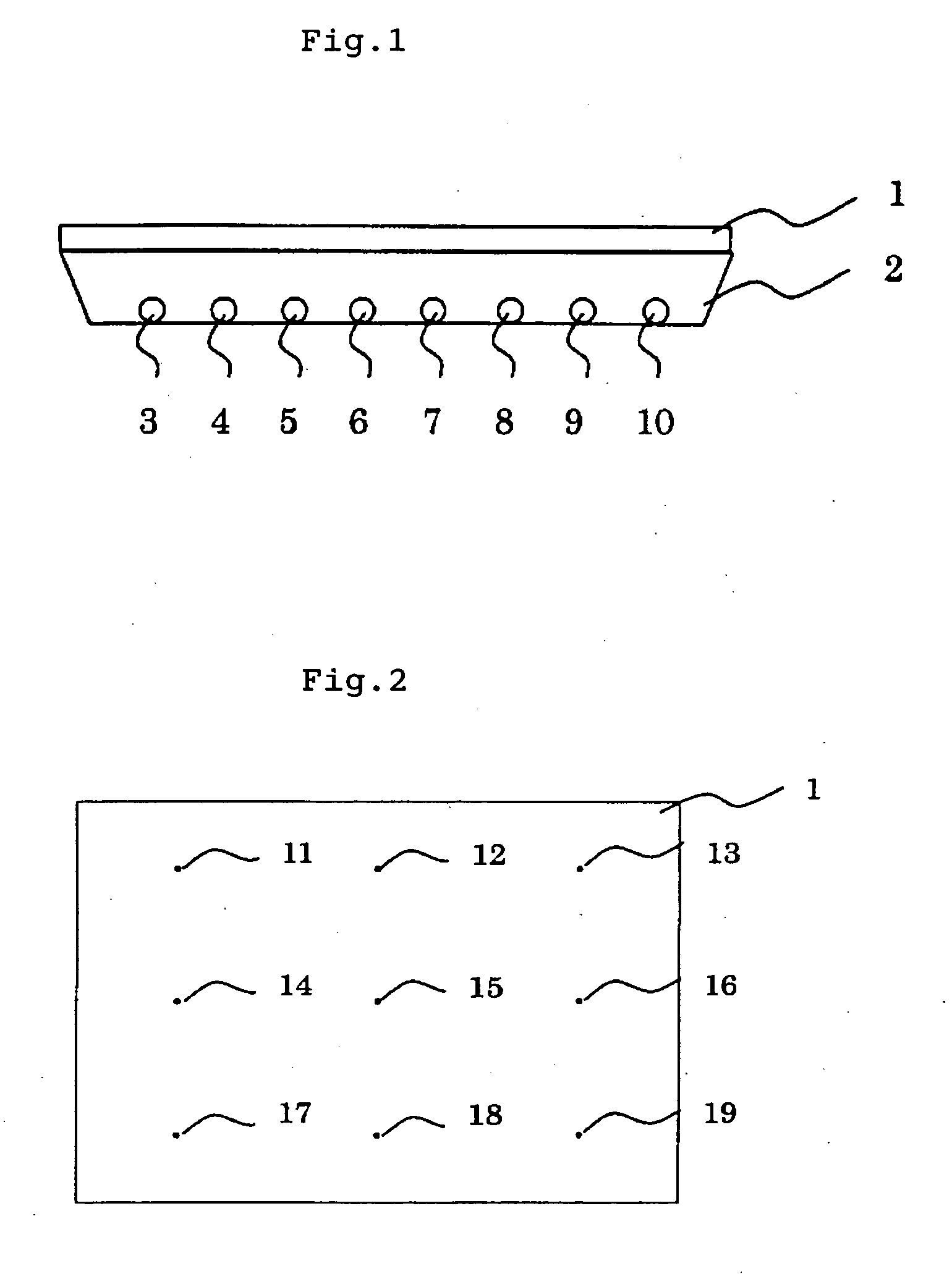
[0294] In Examples 1 to 22 and Comparative Examples 1 to 5, the following properties were evaluated in the following manner. [0295] (1) Total Light Transmittance: Total light transmittance was measured by use of a flat-plate test piece having a size of 50 mm×50 mm and a thickness of 2 mm and the hazemeter NDH 2000 of Nippon Denshoku Industries Co., Ltd. in accordance with JIS K-7361. [0296] (2) Average Brightness: A test piece having a size of 150 mm×150 mm and a thickness of 2 mm was incorporated into a direct backlight unit used in the 10.4-inch TFT color liquid crystal display device module (NL6448CC33-30W) of NEC Corporation. Brightness (cd / m2) was measured at 9 points on the test piece by use of the brightness photometer BM-7 of Topcon Corporation, and the average thereof was taken as average brightness. A device for evaluating the average brightness is shown in FIGS. 1 and 2. Test p...

example 20

[0330] In polycarbonate resin powder (refractive index: 1.59) obtained from bisphenol A and phosgene and having a viscosity average molecular weight of 23,900, polymeric fine particles, heat stabilizers, an ultraviolet absorber and a fluorescent whitening agent were mixed in the amounts shown in Table 4. The resulting powder was melt-extruded into a polycarbonate resin sheet (light diffusion sheet) having a thickness of 2 mm and a width of 1,000 mm by use of a vented T-die extruder at an extruder temperature of 250 to 300° C. and a die temperature of 260 to 300° C. with a degree of vacuum in the vent portion kept at 26.6 kPa. An acrylic resin coating A prepared in accordance with the following composition (solid concentration of coating: 14 wt %) was applied to a surface of the obtained sheet by flow coating. After left to stand at room temperature for 25 minutes, the coated sheet was dried by heating for 40 minutes in a hot air circulating dryer of 120° C. to give a transparent coa...

example 22

[0338] In polycarbonate resin powder (refractive index: 1.59) obtained from bisphenol A and phosgene and having a viscosity average molecular weight of 23,900, polymeric fine particles, heat stabilizers, an ultraviolet absorber and a fluorescent whitening agent were mixed in the amounts shown in Table 4. The resulting powder was fed into an extruder having a screw diameter of 120 mm and molten at 250 to 300° C. with a degree of vacuum in the vent portion kept at 26.6 kPa. Meanwhile, to an auxiliary extruder having a screw diameter of 50 mm, an ultraviolet-absorber-containing polycarbonate resin composition prepared by mixing 100 parts by weight of polycarbonate resin obtained from bisphenol A and phosgene and having a viscosity average molecular weight of 24,300 with 3 parts by weight of 2-(4,6-diphenyl-1,3,5-triazine-2-yl)-5-(hexyl)oxy-phenol (product of Ciba-Geigy Japan Ltd., trade name: TINUVIN 1577FF) as an ultraviolet absorber and extruding and granulating the mixture was fed, ...


PUM

PropertyMeasurementUnit
Lengthaaaaaaaaaa
Lengthaaaaaaaaaa
Percent by massaaaaaaaaaa

Abstract

There is provided a direct backlight type liquid crystal display device having high light diffusability, keeping excellent color and having high brightness. The direct backlight type liquid crystal display device is a direct backlight type liquid crystal display device comprising: a backlight source, a light diffusion sheet which may have a protective film on a surface thereof which faces the backlight source or both surfaces thereof as desired, a light ray adjusting film, and a liquid crystal panel, wherein the light diffusion sheet is formed from a composition comprising predetermined amounts of (C) at least one heat stabilizer (component C) selected from the group consisting of a phosphate compound (component C-1), a phosphate compound (component C-2) and a phosphonite compound (component C-3), (D) an ultraviolet absorber (component D) and (E) a fluorescent whitening agent (component E), based on 100 parts by weight of the total of (A) an aromatic polycarbonate resin (component A) and (B) polymeric fine particles (component B) having an average particle diameter of 0.01 to 50 μm.

Description

TECHNICAL FIELD [0001] The present invention relates to a light diffusion sheet for a direct backlight formed from a polycarbonate resin composition which has its discoloration in a molten state inhibited, retains excellent color even when exposed to heat and light and has its brightness improved by optimizing a heat stabilizer to be used and minimizing light absorption, and to a liquid crystal display device using the light diffusion sheet. BACKGROUND ART [0002] As a light diffusion sheet that is a constituent of a backlight unit used as a light source for various liquid crystal display devices such as a liquid crystal television, a light diffusion sheet formed from a resin composition prepared by adding a light diffusing agent to a matrix resin such as an acrylic resin or a polycarbonate resin is used. [0003] For liquid crystal display devices such as liquid crystal televisions whose size has been increasing to 15 to 39 inches in recent years, a direct backlight system has been be...

Claims


Application Information

Patent Timeline
IPC IPC(8): G02F1/1335G02B27/10G01D11/28C08L69/00G02B5/02G02F1/13357
CPCC08L69/00Y10T428/1036G02B5/0278G02F1/133606G02F2001/133607G02F2001/133614G02F2201/086G02F2201/50G02F2203/60G02B5/0242Y10T428/10Y10T428/26Y10T428/254Y10T428/25C08L2666/02C09K2323/00C09K2323/03G02F1/133607G02F1/133614G02B5/02G02F1/1335
Inventor SOGO, ISAOANDO, MASATOTAKEO, MITSUHIROMAEDA, KOJIJINNO, MASANAO
Owner TEIJIN KASEK KK
Learn More