DWDM CATV return system with up-converters to prevent fiber crosstalk

a technology of up-converters and fiber crosstalk, which is applied in the direction of multiplex communication, electrical equipment, electromagnetic transmission, etc., can solve the problems of complex external modulation, and inability to provide the inherent side mode rejection of multiplexing wdm, so as to minimize crosstalk and minimize the length of optical fibers. , the effect of minimizing the length of optical fibers

Inactive Publication Date: 2006-07-27
BROADBAND ROYALTY
View PDF17 Cites 54 Cited by
  • Summary
  • Abstract
  • Description
  • Claims
  • Application Information

AI Technical Summary

Benefits of technology

[0024] In the invention herein, SRS crosstalk is minimized by minimizing the length of optical fibers that use WDM to carry optical signals having low frequency carrier signals. Also, SRS crosstalk is minimized by providing separate fibers for optical signals with low frequency carrier signals, so that, wavelength division multiplexing (WDM) is only used for light beams that exclusively use high frequency carrier signals. Prior to DWDM, the carrier frequencies of light beams are increased, so that, after the light beam is multiplexed with other beams, cross talk due to SRS will be minimized. In addition, in order to further reduce cross-talk between information in wav

Problems solved by technology

This option is expensive when installing a new system even though optical fibers are relatively inexpensive, because of the large number of fibers that are required in the fiber tree network, but it is impractical to upgrade a system in this manner because of the large expense of installing additional fiber all the way back to the head-end whenever another node is added as system.
Alternatively, a multi-branch optical coupler can be used for multiplexing multiple beams, but does not provide the inherent side mode rejection of a multiplexing WDM.
The wavelength of the laser and of the WDM must be precisely matched, but the wavelengths of both the lasers and WDM are temperature dependent, so that, the wavelength separation between beams must be sufficient, so that, temperature fluctuations will not cause loss of signal through the WDM.
Chirping can be eliminated by using external modulation of the laser beam, but external modulation is more complex and expensive.
Thus, the separation between optical wavelengths of light beams in a WDM system is limited by fluctuations of the laser wavelength due to temperature fluctuations and chirping

Method used


Image

  • DWDM CATV return system with up-converters to prevent fiber crosstalk
  • DWDM CATV return system with up-converters to prevent fiber crosstalk
  • DWDM CATV return system with up-converters to prevent fiber crosstalk

Examples


Embodiment Construction

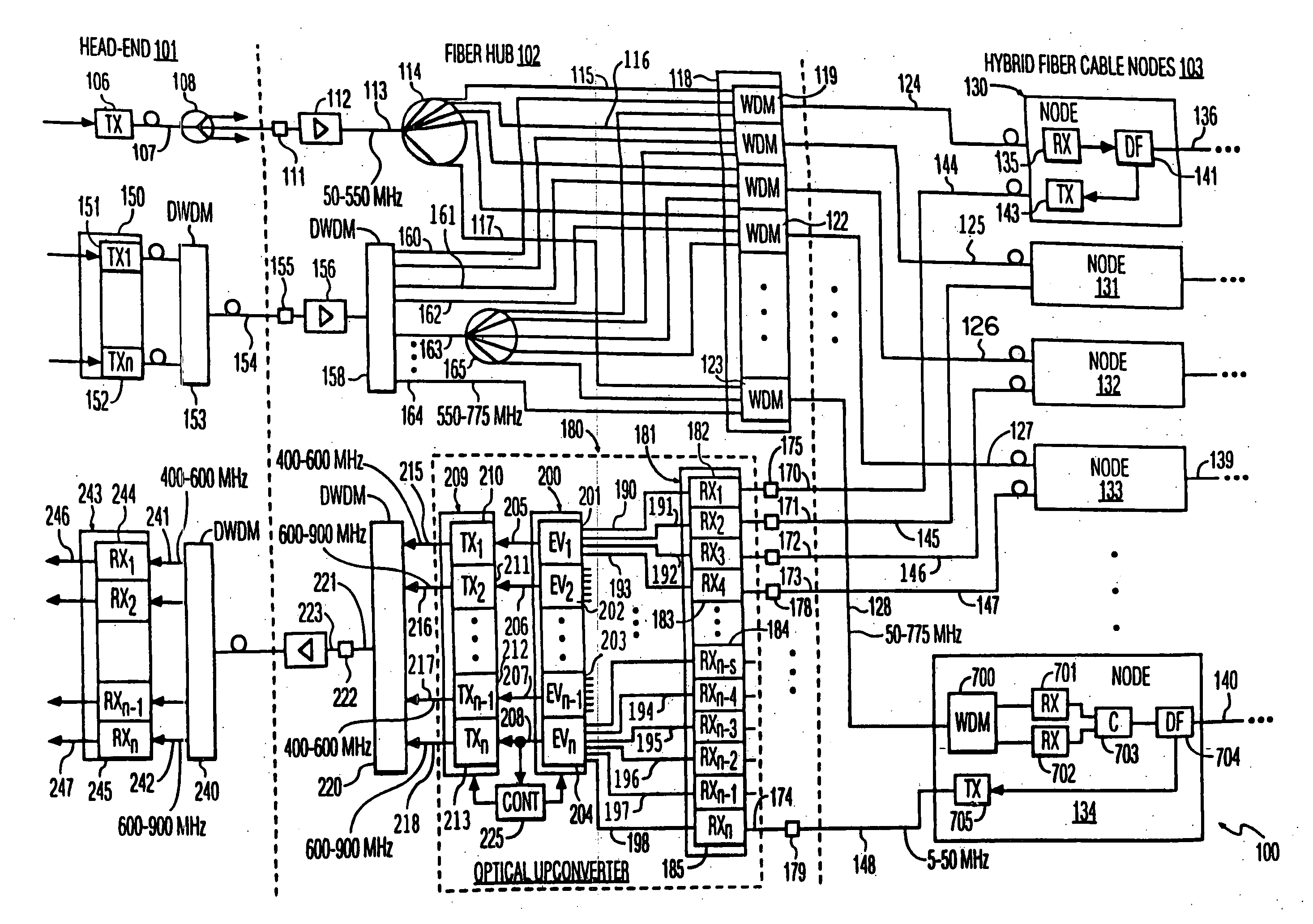
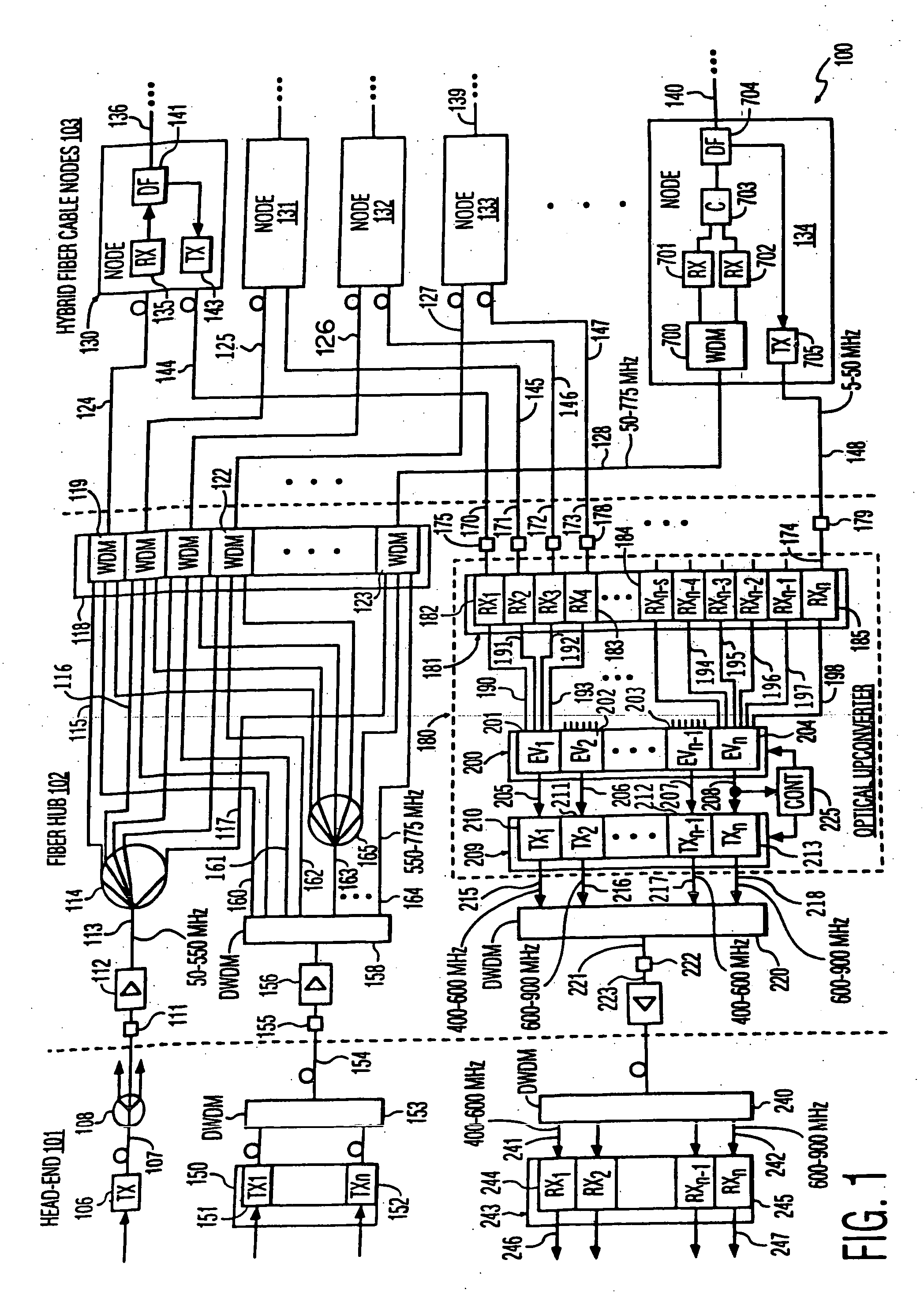
[0070]FIG. 1 illustrates relevant portions of a hybrid fiber cable television network of 100 the invention. At a head-end 101 (see FIG. 6), an optical transmitter 106 (see FIG. 2) converts an electronic multicarrier signal for analog television broadcast, into a optical multicarrier signal in optical fiber 107. Optical splitter 108 splits the optical signal up into a plurality of optical signals in different optical fibers for respective fiber-hubs such as fiber 113. The signal transmitted by transmitter 106 is a conventional analog television broadcast signal typical of cable television systems as described above with a carrier frequency band of nominally 50=550 MHz for NTSC and 65-550 MHz for PAL broadcasts.

[0071] Fiber 113 is connected to a fiber-hub 102 (see FIG. 7) by optical connector 111. An optical amplifier 112 amplifies the broadcast signal in fiber 113. The optical amplifier may be positioned in the head-end, intermediate between the head-end and the fiber-hub, or in the...


PUM


Abstract

A hybrid fiber cable network includes multiple nodes, each of which receives a first multi-carrier return signal from multiple customers with carrier signals in a first frequency band. In a fiber-hub, one or more first multi-carrier signals are converted into a second multi-carrier signal with carrier signals in a second band. Each information signal modulates a different higher frequency carrier signal in the second signal. A multitude of second multi-carrier signals are converted into optical signals with different optical wavelengths, multiplexed onto an optical fiber, and transmitted to the head-end. The first frequency band is below 200 MHz, preferably from 5 to 50 MHz. The second frequency band is above 200 MHz, preferably between 300 and 1200 MHz to reduce crosstalk due to stimulated Raman scattering (SRS). Preferably, each second frequency band is no more than one octave wide, and more preferably, no more than one half an octave wide.

Description

CROSS REFERENCE TO RELATED APPLICATIONS [0001] This application is a continuation of and claims priority under 35 U.S.C. § 119 to co-pending U.S. application Ser. No. 09 / 474,299, filed Dec. 29, 1999, which was a continuation of U.S. provisional application 60 / 135,609, filed May 24, 1999, which is hereby incorporated in whole by reference.FIELD OF THE INVENTION [0002] The invention is related to the field of broadband hybrid fiber cable communication systems such as cable television systems and is most closely related to laser optical communication links for return signals in such systems using dense wavelength division multiplexing. BACKGROUND OF THE INVENTION [0003] Commonly in cable television systems (CATV), television programs are broadcast from a central head-end to a multitude of customers. The programs are distributed from the head-end through an branching tree-like, optical fiber network to a multitude of local hybrid fiber cable nodes (HFCNs) in respective communities. Then...

Claims


Application Information

Patent Timeline
IPC IPC(8): H04J14/00
CPCH04B10/25751H04J14/0226H04J14/0282H04J14/0298H04N7/22H04J14/0232H04J14/0246H04J14/0247H04J14/025H04J14/0252
Inventor SCHEMMANN, MARCEL F.C.MUTALIK, VENKATESH G.
Owner BROADBAND ROYALTY
Why Eureka
Try Eureka