Integrated planar microfluidic bioanalytical systems

a microfluidic and bioanalytical technology, applied in the direction of instruments, optical elements, optical waveguide light guides, etc., can solve the problems of serious limitations, the enormity of the analytical problem is clearly evident, and the protein analysis is an extremely difficult task, and achieve rapid, automated and high peak capacity separation

Inactive Publication Date: 2006-08-03
BRIGHAM YOUNG UNIV
View PDF4 Cites 37 Cited by
  • Summary
  • Abstract
  • Description
  • Claims
  • Application Information

AI Technical Summary

Benefits of technology

[0023] The present invention is a system and method for performing rapid, automated and high peak capacity separations of complex protein mixtures through the combination of fluidic and electrical elements on an integrated circuit, utilizing planar thin-film micromachining for both fluidic and electrical components.

Problems solved by technology

Unfortunately, protein analysis is an extremely challenging task because of the sheer number of proteins in biological systems and their dynamic nature.
Considering that current studies place the number of genes in the human genome to be about 22,000 and that there are many more proteins than genes, the enormity of the analytical problem is clearly evident.
Although 2-D gel electrophoresis can resolve more than 1,000 proteins in an analysis, it has some serious limitations.
First, the resolving power of 2-D gel electrophoresis is insufficient to separate the numerous proteins that may be important in the profile; i.e., 1,000 proteins compared to a possible 1,500,000.
Second, the reproducibility of the technique is insufficient, making it difficult to detect differences in protein expression reflected in two different gels.
Third, this technique is time-consuming (i.e., as much as several days) and labor-intensive.
These stains have variable sensitivities to protein structure and mass present in the spot and, therefore, are not reliably quantitative.
While the analysis times for this system were an improvement over the several days often required for 2-D gel electrophoresis, the ˜8 h separation time is still slower than desired.
Nevertheless, the wide spacing (1 mm) and small number (10) of electrophoresis channels in this format limits performance and complicates detection.
While miniaturization has the potential to revolutionize chemical separation methods as it did with integrated circuits, thus far the impact of microfabrication on separations has been modest.
While typically providing simplified and low-cost device fabrication, polymeric substrates are disadvantageous in terms of compatibility with conventional Si processing methods that may require elevated temperatures, for example in thin-film deposition, which would hamper the direct integration of planar polymeric devices with some electronics, detection instrumentation, etc.
To date, little success has been seen in fabricating functional microfluidic systems on silicon substrates.
The programmed control of surface temperature in thermocapillary pumping, or surface free energy using tailored self-assembled monolayers can enable liquid flow, but these approaches suffer from a significant level of device fabrication and surface modification complexity.
However, in the former approach, the electrolysis solution directly contacts the liquid being pumped, potentially causing contamination, while the latter method is complicated by the need to microfabricate a thin membrane for each pump.
For these modules, the need for external pressure and vacuum sources to actuate the membranes makes the entire system difficult to miniaturize.
Moreover, the use of PDMS membranes in direct contact with pumped fluids is problematic for LC, because PDMS acts as a hydrophobic stationary phase in chromatography.
Issues not yet addressed with this form of pumping include challenges associated with reproducible etching of very shallow channel arrays and reliable thermal attachment of a cover plate to create large bundles of integrated microcapillaries to achieve suitable pressures.
One of the challenges with increasingly parallel microfluidic arrays is the two-dimensional nature of planar microchip systems.
Some efforts have been directed at creating three-dimensional, layered microfluidic manifolds, but the initial attempts were quite cumbersome in terms of both fabrication and fluidics.
More sophisticated recent work has utilized multiple-layer devices to create fluidic manifolds with increased liquid routing complexity.
However, these systems utilize via holes through layers that can contribute to dead volume, and use materials such as PDMS that have poor stability in many solvents and reduced compatibility with planar Si micromachining processes.

Method used


Image

  • Integrated planar microfluidic bioanalytical systems
  • Integrated planar microfluidic bioanalytical systems
  • Integrated planar microfluidic bioanalytical systems

Examples


Embodiment Construction

[0056] Reference will now be made to the drawings in which the various elements of the present invention will be given numerical designations and in which the invention will be discussed so as to enable one skilled in the art to make and use the invention. It is to be understood that the following description is only exemplary of the principles of the present invention, and should not be viewed as narrowing the claims which follow.

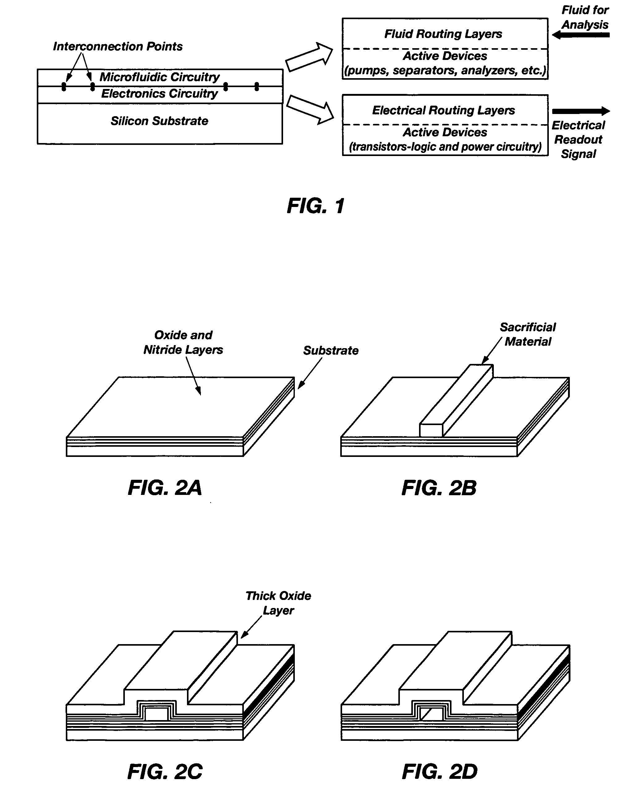
[0057] The present invention is a system and method for integrating microfluidics directly onto electronic systems, thereby making it possible that logic and electric power elements can be built into a microfluidic analysis system. FIG. 1 illustrates the fundamental design concepts of the present invention.

[0058]FIG. 1 is provided as an illustration of a cross section of a substrate showing how microfluidics are combined on the same substrate with microelectronics using thin-film microfabrication techniques. Using flat silicon substrates 10, electronic c...


PUM


Abstract

A system and method for performing rapid, automated and high peak capacity separations of complex protein mixtures through the combination of fluidic and electrical elements on an integrated circuit, utilizing planar thin-film micromachining for both fluidic and electrical components.

Description

CROSS REFERENCE TO RELATED APPLICATIONS [0001] This document claims priority to, and incorporates by reference all of the subject matter included in the provisional patent application docket number 05-01, having Ser. No. 60 / 646,184 and filed on Jan. 20, 2005. This document also claims priority to the co-pending patent application Ser. No. 10 / 868,475 filed on Jun. 15, 2004.BACKGROUND OF THE INVENTION [0002] 1. Field of the Invention [0003] This invention relates generally to microfabrication processes for microfluidics. More specifically, the invention is a system and method of microfabrication that use planar, thin-film microfabrication techniques from which microfluidic and microelectronic components are combined on a substrate to perform bioanalytical microfluidic operations. [0004] 2. Description of Related Art [0005] An increasing need for the detection and quantification of biological molecules in medicine, biochemistry, and biology has driven a rapid expansion in the analysis ...

Claims


Application Information

Patent Timeline
Patent Type & Authority Applications(United States)
IPC IPC(8): G02B6/00
CPCG01N21/05G01N21/6428G02B6/032G02B6/12G02B6/122G02B2006/12138G01N2021/0346
Inventor HAWKINS, AARON R.PEENI, BRIDGETBARBER, JOHNWOOLLEY, ADAM T.SCHMIDT, HOLGERLEE, MILTON L.
Owner BRIGHAM YOUNG UNIV
Why Eureka
Try Eureka