Ultrasonic probe for intra-cavity diagnosis and manufacturing method thereof

a technology of ultrasonic probes and intracavity, which is applied in the field of ultrasonic probes for intracavity diagnosis, can solve the problems of reducing the s/n ratio, affecting the accuracy of ultrasonic diagnosis, and reducing the resolution power of ultrasonic images, so as to achieve ultrasonic diagnosis in a deeper range of the living body, superior to piezoelectric elements, and intelligently arranged

Inactive Publication Date: 2006-08-17
FUJIFILM HLDG CORP +2
View PDF5 Cites 40 Cited by
  • Summary
  • Abstract
  • Description
  • Claims
  • Application Information

AI Technical Summary

Benefits of technology

[0027] The capacitive micromachined ultrasonic transducers are superior to the piezoelectric elements, because the capacitive transducer can be formed integrally on an electric circuit, so the wires can be arranged more smartly as compared to a case using the piezoelectric elements. The capacitive transducer has a wider ultrasonic frequency band than the piezoelectric element, so that it can send and receive the ultrasonic waves of a wider variety of frequenci

Problems solved by technology

Since the available number of ultrasonic transducers to one probe is limited by the permissible thickness of the wiring cable, the resolving power of the ultrasonic image has also been limited.
Beside that, if the wiring cable has a large capacitance, the echo signal will damp.
Mismatching of electric impedance will lower the S/N ratio, and may also cause cross-talk between the wires, which can result in malfunction.
In that case, if the ultrasonic transducers are arranged to set their lateral direction in alignment with an inserting direction of the ultrasonic probe, the ultrasonic probe will have a relatively large hard portion including the ultrasonic transducers, increasing the load on the patient tha

Method used


Image

  • Ultrasonic probe for intra-cavity diagnosis and manufacturing method thereof
  • Ultrasonic probe for intra-cavity diagnosis and manufacturing method thereof
  • Ultrasonic probe for intra-cavity diagnosis and manufacturing method thereof

Examples


Embodiment Construction

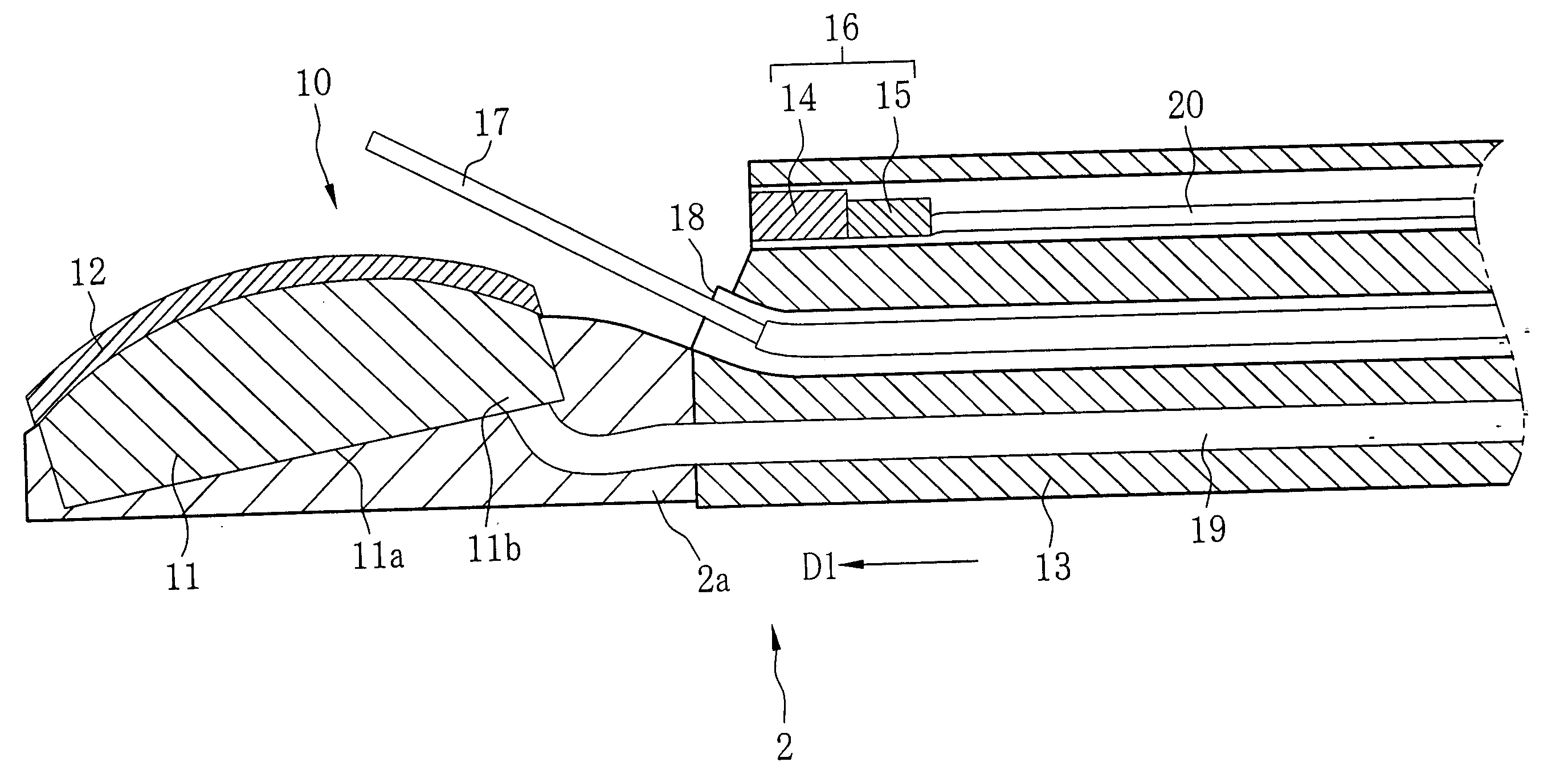
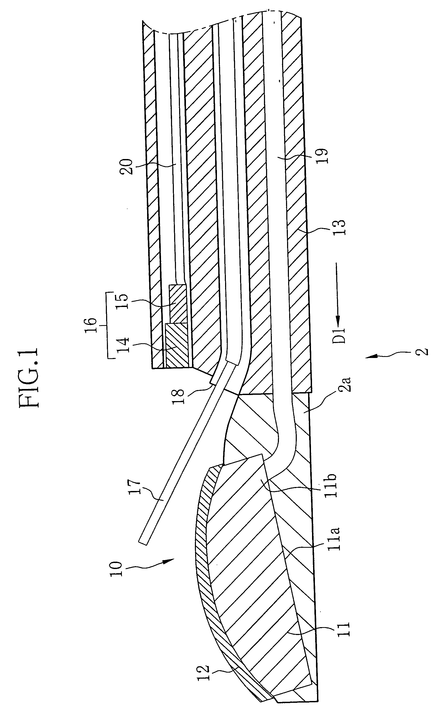
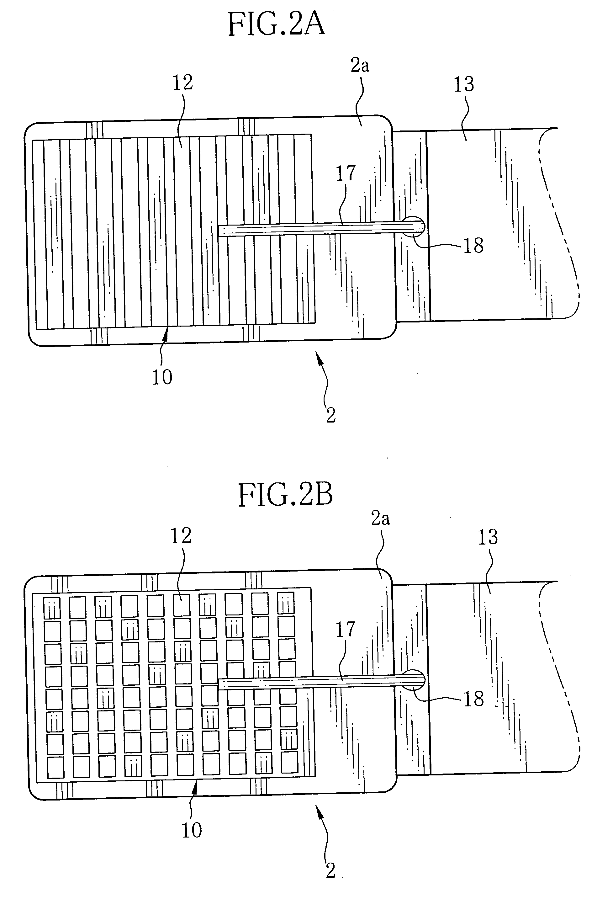
[0049] As shown in FIG. 1, a body cavity diagnostic ultrasonic probe, hereinafter called simply the ultrasonic probe 2, has an ultrasonic transducer array 10 at its tip 2a. The ultrasonic transducer array 10 has an external diameter of about 5 mm to 8 mm, and is of a convex type which is constituted of a number of ultrasonic transducers 12 arranged in an array on a semi-cylindrical supporting member 11. The ultrasonic transducers 12 are arranged in a linear array as shown in FIG. 2A or in a two-dimensional array as shown in FIG. 2B.

[0050] The ultrasonic transducer array 10 is connected to a sheath 13 that has an external diameter of about 7 mm to 10 mm. An imaging device 16 is mounted in an upper portion of the sheath 13. The imaging device 16 is provided with an objective optical system 14 for forming an optical image of an internal body part to investigate, and a CCD 15 for capturing the optical image as an image signal. A channel 18 for putting a piercing needle 17 through it is...


PUM


Abstract

A diagnostic ultrasonic probe for use in body cavities has at its tip an ultrasonic transducer array, which has a layered structure wherein a flexible circuit board, an electric circuit, a backing material, a piezoelectric element array, an acoustic impedance matching layer and an acoustic lens are formed atop another on a supporting member. The electric circuit includes at least one of amplifiers for amplifying echo signals from ultrasonic transducers, switches for switching over between sending the echo signals from the ultrasonic transducers and receiving drive signals for exciting the ultrasonic transducers, a multiplexer for selective-switching between the echo signals as well as between the drive signals, an A/D converter for converting the echo signals from an analog form to a digital form, and a D/A converter for converting the drive signals from a digital form to an analog form.

Description

FIELD OF THE INVENTION [0001] The present invention relates to an ultrasonic probe for intra-cavity diagnosis having an ultrasonic transducer array, which is inserted into body cavities to emit ultrasonic waves toward a necessary internal body part and receive echo signals from the body part, and a manufacturing method of the ultrasonic probe. BACKGROUND ARTS [0002] Medical diagnosis that utilizes ultrasound imaging has recently been widely used in medical fields. The ultrasonic image is obtained by emitting ultrasound from an ultrasonic probe toward a necessary body part and detecting echo from the body part as electric echo signals by use of an ultrasound observing device that is connected to the ultrasonic probe through a connector. The ultrasonic probes may be classified roughly into an intra-cavity diagnostic type that is inserted in a body cavity, and an extra-cavity diagnostic type that is moved on the body surface. As a known driving methods for the intra-cavity diagnostic u...

Claims


Application Information

Patent Timeline
IPC IPC(8): A61B8/14
CPCA61B8/12A61B8/445A61B8/4488
Inventor KIMURA, KOICHITANAKA, TOSHIZUMI
Owner FUJIFILM HLDG CORP
Why Eureka
Try Eureka