
Organic electroluminescent element

a technology of electroluminescent elements and organic materials, applied in the direction of discharge tube/lamp details, discharge tube luminescent screens, discharge tubes/lamp details, etc., can solve the problems of difficult observation of tg, deterioration of thin film shape, and inability to achieve high efficiency, etc., to achieve good driving stability, improve driving stability and heat resistance, and improve the effect of stability

Inactive Publication Date: 2006-08-24
NIPPON STEEL CHEMICAL CO LTD
View PDF5 Cites 16 Cited by
  • Summary
  • Abstract
  • Description
  • Claims
  • Application Information

AI Technical Summary

Benefits of technology

[0011] In contemplating applications of organic EL elements utilizing phosphorescence to display elements such as flat panel displays and illumination, the essential requirement is to improve the driving stability and heat resistance. Under the circumstances, an object of this invention is to provide an organic EL element showing high efficiency and good driving stability.
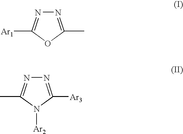
[0027] The azole compounds useful for this invention are characterized by having both oxadiazole and triazole structures. According to the information available to date, compounds in which the oxadiazole structure or the triazole structure exists singly (for example, PBD and TAZ) are highly crystalline, unstable when formed into thin films and unsuited for practical use as materials for organic EL elements. The high crystallinity here is presumably due to a strong intermolelcular interaction because of the presence of highly polar functional groups such as oxadiazole and triazole. This consideration supports an assumption that the designed coexistence of different kinds of highly polar functional groups in a molecule endows the molecule with a function of canceling each other's polarity and suppressing the intermolecular interaction and results in improved stability of thin film.

Problems solved by technology

Thereafter, a europium complex was used in an attempt to utilize the triplet state, but a high efficiency was not achieved.
However, a highly efficient organic EL element using the phosphorescent molecule [Ir(Ppy)3] described in the aforementioned article shows driving stability that is not enough for the practical use at the present time.
This deterioration of the thin film shape probably results from the crystallization (or cohesion) of a thin organic non-crystalline film caused by heat generated during driving of the element and low heat resistance from low glass transition temperature (Tg) of the material.
These compounds readily undergo crystallization or cohesion on account of their high symmetry and low molecular weight thereby deteriorating the thin film shape and, besides, their Tg is difficult to even observe because of high crystallinity.
The instability of the thin film shape inside the luminescent layer like the one noted above exerts a bad influence such as shortening of the driving life of the element and lowering of the heat resistance.
For the aforementioned reasons, a big problem facing organic EL elements utilizing phosphorescence at the present time is the driving stability of the element.
However, the cited elements all face the aforementioned problems.

Method used


Image

  • Organic electroluminescent element
  • Organic electroluminescent element
  • Organic electroluminescent element

Examples


synthetic example 1

Synthesis of 3-[4-(phenyl-1,3,4-oxadiazolyl-(5))-phenyl]-4,5-diphenyl-1,2,4-triazole (Hereinafter Referred to as POT)

[0069] The reactions involved in the synthesis are shown below.

[0070] The reaction of compound (6) with compound (8) to give POT is described below.

[0071] In a 1000-ml four-necked flask were placed 43.6 g (0.150 mole) of compound (6), 64.8 g (0.300 mole) of compound (8) and 493.1 g of pyridine and the mixture was heated to 114° C. and heated there under reflux for 2 hours. After the reaction, the reaction mixture was thrown into 3000 ml of methanol and the precipitated crystals were collected by filtration, washed with 1500 ml of methanol and dried at 100° C. under reduced pressure to give 1.3 g of dried crystals. The crystals were recrystallizerd three times from dimethylformamide to give 31.0 g of purified crystals of POT; purity 99.97% (HPLC area ratio), mass analysis value 441, melting point 273.0° C., yield 46.8%. POT is compound No.1 in Table 1.

[0072] The r...

synthetic example 2

Synthesis of 3,4-bis[4-(2-phenyl-1,3,4-oxadiazolyl-(5))-phenyl]-5-phenyl-1,2,4-triazole (Hereinafter Referred to as 3,4-BPOT)

[0074] The reactions involved in the synthesis are shown below.

[0075] The reaction of compound (14) with compound (10) to give 3,4-BPOT is described below.

[0076] In a 200-ml four-necked flask were placed 6.1 g (0.011 mole) of compound (14), 4.9 g (0.034 mole) of compound (10) and 73.3 g of pyridine and the mixture was heated to 117° C. and heated there under reflux for 2 hours. After the reaction, 100.9 g of methanol was added to the mixture and the precipitated crystals were collected by filtration and recrystallized from methylene chloride to give 3.6 g of purified crystals of 3,4-BPOT: purity 99.16% (HPLC area ratio), mass analysis value 585, melting point 324.0° C., yield 55.9%. 3,4-BPOT is compound No. 55 in Table 8.

[0077] The result of the IR analysis of 3,4-BPOT is shown below.

[0078] IR (KBr) 3448, 3060, 2920, 2856, 1932, 1612, 1582, 1550, 1502, 1...

synthetic example 3

Synthesis of 3,5-bis[4-(2-phenyl-1,3,4-oxadiazolyl-(5))-phenyl]-5-phenyl-1,2,4-triazole (Hereinafter Referred to as 3,5-BPOT)

[0079] The reactions involved in the synthesis are shown below.

[0080] The reaction of compound (19) with compound (10) to give 3,5-BPOT is described below. In a 300-ml four-necked flask were placed 5.6 g (0.011 mole) of compound (19), 4.2 g (0.030 mole) of compound (10) and 87.9 g of pyridine and the mixture was heated to 117° C. and heated there under reflux for 2 hours. After the reaction, 136.5 g of methanol was added to the mixture and the precipitated crystals were collected by filtration and recrystallized from methylene chloride to give 3.3 g of purified crystals of 3,5-BPOT: purity 99.31% (HPLC area ratio), mass analysis value 585, melting point 344.1° C., yield 51.3%. 3,5-BPOT is compound No. 37 in Table 5.

[0081] The result of the IR analysis of 3,5-BPOT is shown below.

[0082] IR (KBr) 3452, 3060, 2924, 1612, 1548, 1472, 1450, 1412, 1314, 1270, 11...


PUM


Abstract

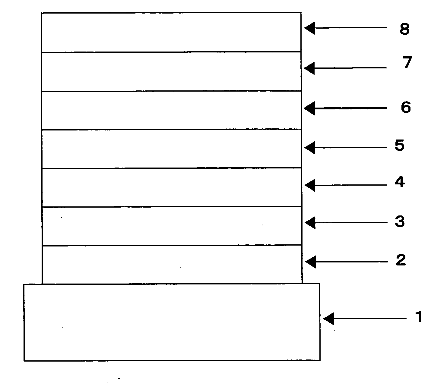
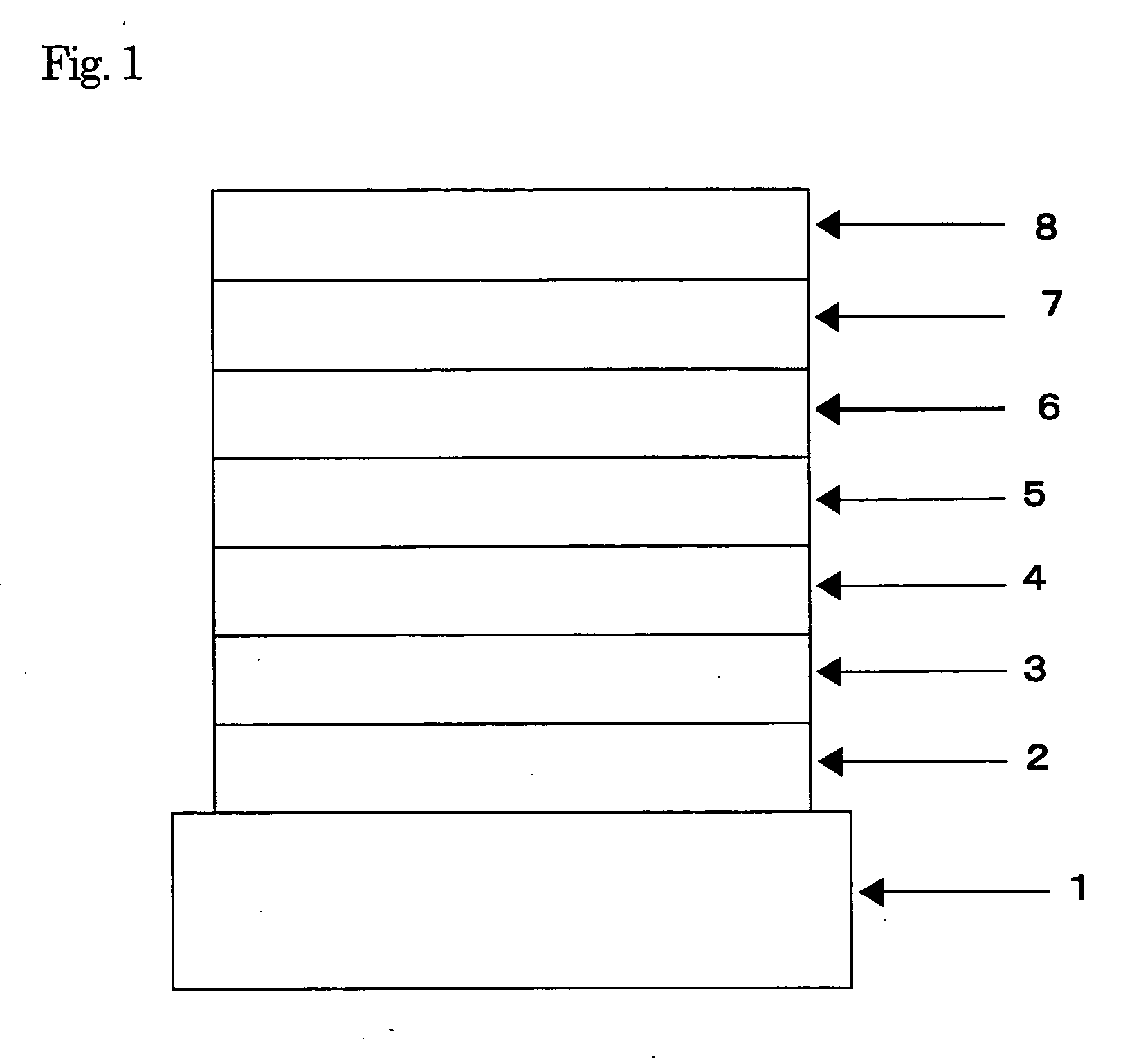
This invention relates to an organic electroluminescent element comprising a substrate, an anode, an organic layer and a cathode placed in layer one upon another; at least one layer in the organic layer is a luminescent layer comprising a host agent and a doping agent and an azole compound having an oxadiazole structure and a triazole structure in its molecule is used in at least one layer in the organic layer. This azole compound is used as a host agent in the luminescent layer and it can also be used in a hole blocking layer or electron transporting layer. This organic EL element is suitable for use in full-color and multicolor panels and shows a higher luminous efficiency and better driving stability than EL elements utilizing the luminescence from the singlet state.

Description

FIELD OF TECHNOLOGY [0001] This invention relates to an organic electroluminescent element and, more particularly, to a thin film type device which emits light when an electric field is applied to its luminescent layer comprising organic compounds. BACKGROUND TECHNOLOGY [0002] In the development of electroluminescent elements utilizing organic materials (hereinafter referred to as organic EL elements), elements devised by optimizing the kind of electrode and providing a hole transporting layer composed of an aromatic diamine and a luminescent layer composed of 8-hydroxyquinoline aluminum complex in the form of thin films between the electrodes for the purpose of improving the efficiency of electric charge injection from the electrode achieved marked improvement in luminous efficiency compared with the conventional elements utilizing single crystals of anthracene and the like (Appl. Phys. Lett., vol. 51, p. 913, 1987) and the ensuing developmental efforts have been directed to practi...

Claims


Application Information

Patent Timeline
IPC IPC(8): H01J1/62C09K11/06H01L51/00H01L51/50H05B33/14H05B33/22
CPCC09K11/06C09K2211/1048C09K2211/1059H01L51/0067H01L51/007H01L51/5012H01L51/5048H01L51/5096H05B33/14H10K85/6565H10K85/654H10K50/14H10K50/18H10K50/11
Inventor YOSHITAKE, OSAMUMIYAZAKI, HIROSHISAIKAWA, SHINYAYAMADA, YU
Owner NIPPON STEEL CHEMICAL CO LTD
Learn More