
Electrically conductive polymer composition and solid electrolytic capacitor using the same

a technology of polymer composition and solid electrolytic capacitor, which is applied in the direction of electrolytic capacitor, capacitor electrode, liquid electrolytic capacitor, etc., can solve the problems of low resistance, low stability at high temperatures, and inability to meet the needs of high temperature stability, so as to reduce the resistance and low resistance

Active Publication Date: 2006-08-24
TOKIN CORP
View PDF8 Cites 17 Cited by
  • Summary
  • Abstract
  • Description
  • Claims
  • Application Information

AI Technical Summary

Benefits of technology

[0007] It is therefore an object of this invention to provide an electrically conductive polymer composition capable of obtaining a coating film that is made of a water-soluble conductive polymer containing EDT and has a reduced resistivity, and further, that can maintain such a low resistivity even in a high-temperature environment.
[0008] It is another object of this invention to provide a solid electrolytic capacitor having excellent ESR characteristics by applying the coating film of the foregoing conductive polymer composition.
[0009] It is still another object of this invention to provide a surface-mount transmission line element having excellent ESR characteristics by applying the coating film of the foregoing conductive polymer composition.

Problems solved by technology

However, at present, even in the using method like (A), the conductive polymer formed by the soluble conductive polymer solution can only form a polymer layer having a resistivity that is several to 100 times higher or more as compared with the conductive polymer formed only by the chemical oxidation polymerization and, further, the stability at high temperatures is also inferior thereto and the resistance increases in a short time, which has been a problem in application to the solid electrolytic capacitor.
Further, it has still been a problem that the stability at high temperatures is inferior thereto.
However, those polymers have high electrical resistances and notably increase in electrical resistance at temperatures of about 100° C., and therefore, cannot be applied to solid electrolytes of capacitors as they are.

Method used


Image

  • Electrically conductive polymer composition and solid electrolytic capacitor using the same
  • Electrically conductive polymer composition and solid electrolytic capacitor using the same
  • Electrically conductive polymer composition and solid electrolytic capacitor using the same

Examples


example 1

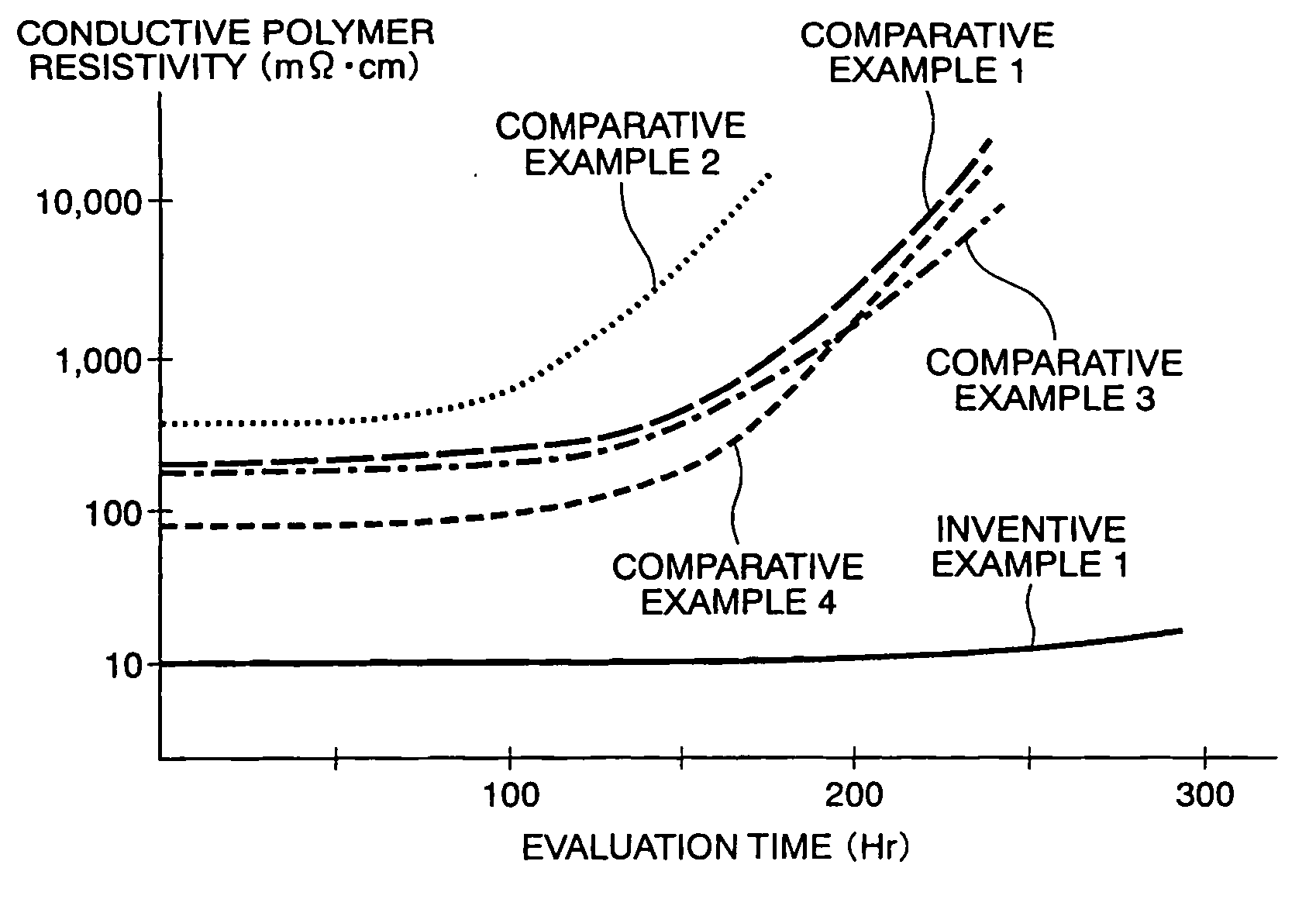
[0027] In Example 1 of this invention, the weight ratio composition of respective materials to be used was set to EDT:1, PSSA:2.6, NSA:1.5, and oxidant:1 given that pure water was 100. PSSA was used in the form of a 20% aqueous solution of PSSA having an average molecular weight of 14,000, NSA was used in the form of a 10% aqueous solution, and ammonium peroxodisulphate (hereinafter referred to as “APS”) powder was used as the oxidant. When the aqueous solution was used, the weight ratio was given as a value corresponding to the solid part thereof. The foregoing materials ad the pure water were put into a container and then stirred with a stirrer so that polymerization proceeded. In this event, APS serving as the oxidant was added dividedly after uniformly stirring and mixing EDT, PSSA, and NSA being the base materials. This is because if a large amount of the oxidant is added at one time, variation in molecular weight of a conductive polymer to be obtained increases so that there a...

example 2

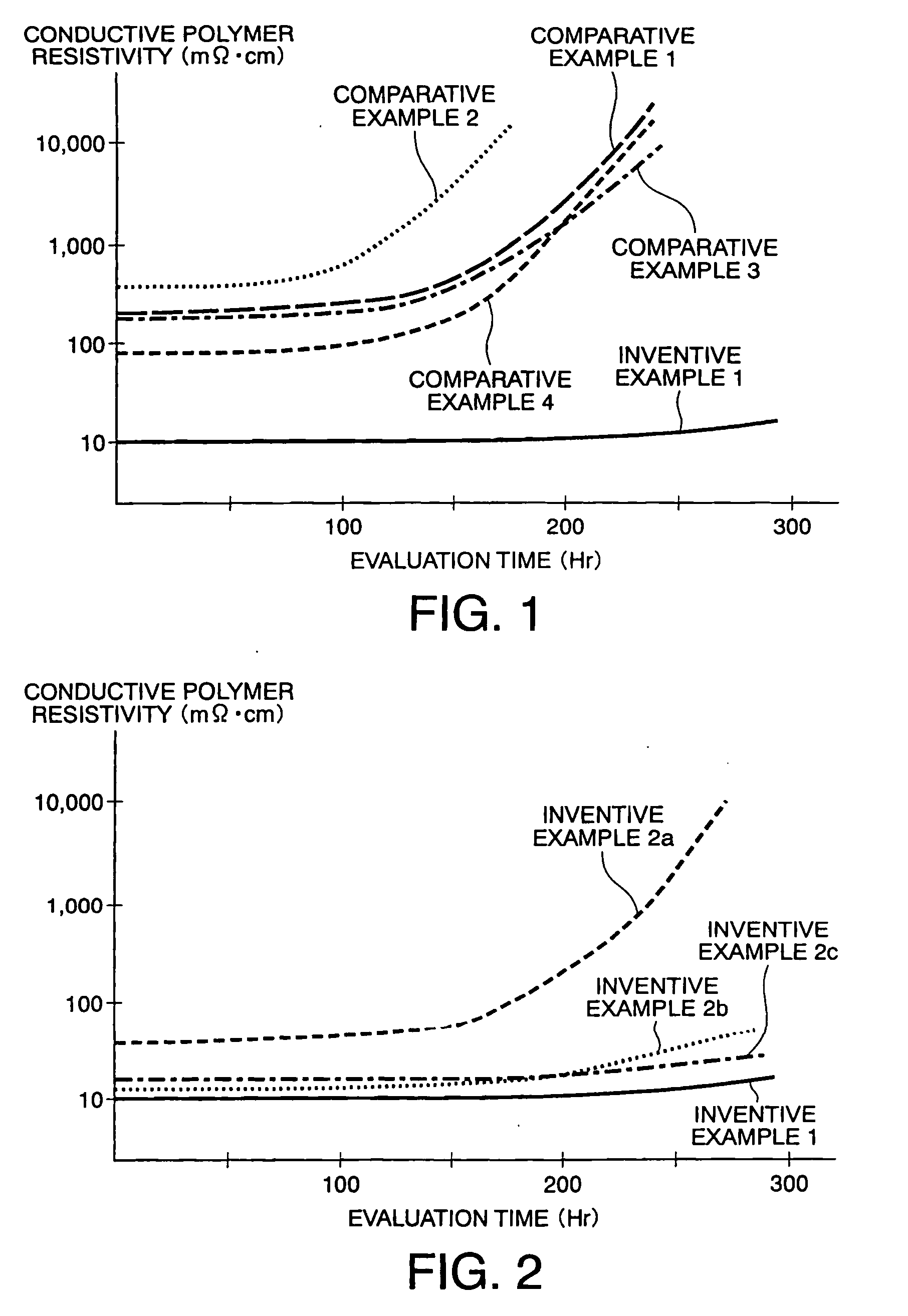
[0029] In Example 2 of this invention, conductive polymer aqueous solutions were produced in the same manner as in Example 1 except that the weight composition ratios of NSA were set to 0.5. 1.0, and 2.0 relative to pure water 100, respectively (hereinafter, the respective compositions will be referred to as Examples 2a, 2b, and 2c). These solutions were dropped on glass plates to obtain coating films like in Example 1. The resistivity of each coating film is shown in Table 2 below in comparison with Example 1. FIG. 2 shows changes in resistivity of those coating films when they were left standing in an atmospheric atmosphere at 150° C.

TABLE 2MeasurementInventiveInventiveInventiveInventiveObjectExample 1Example 2aExample 2bExample 2cResistivity10 mΩ· cm50 mΩ· cm13 mΩ· cm17 mΩ· cm

[0030] It is understood from Table 2 that although there is almost no difference between Example 1 and Examples 2a to 2c, the coating film of Example 1 exhibits the lowest resistivity and, further, it is u...

example 3

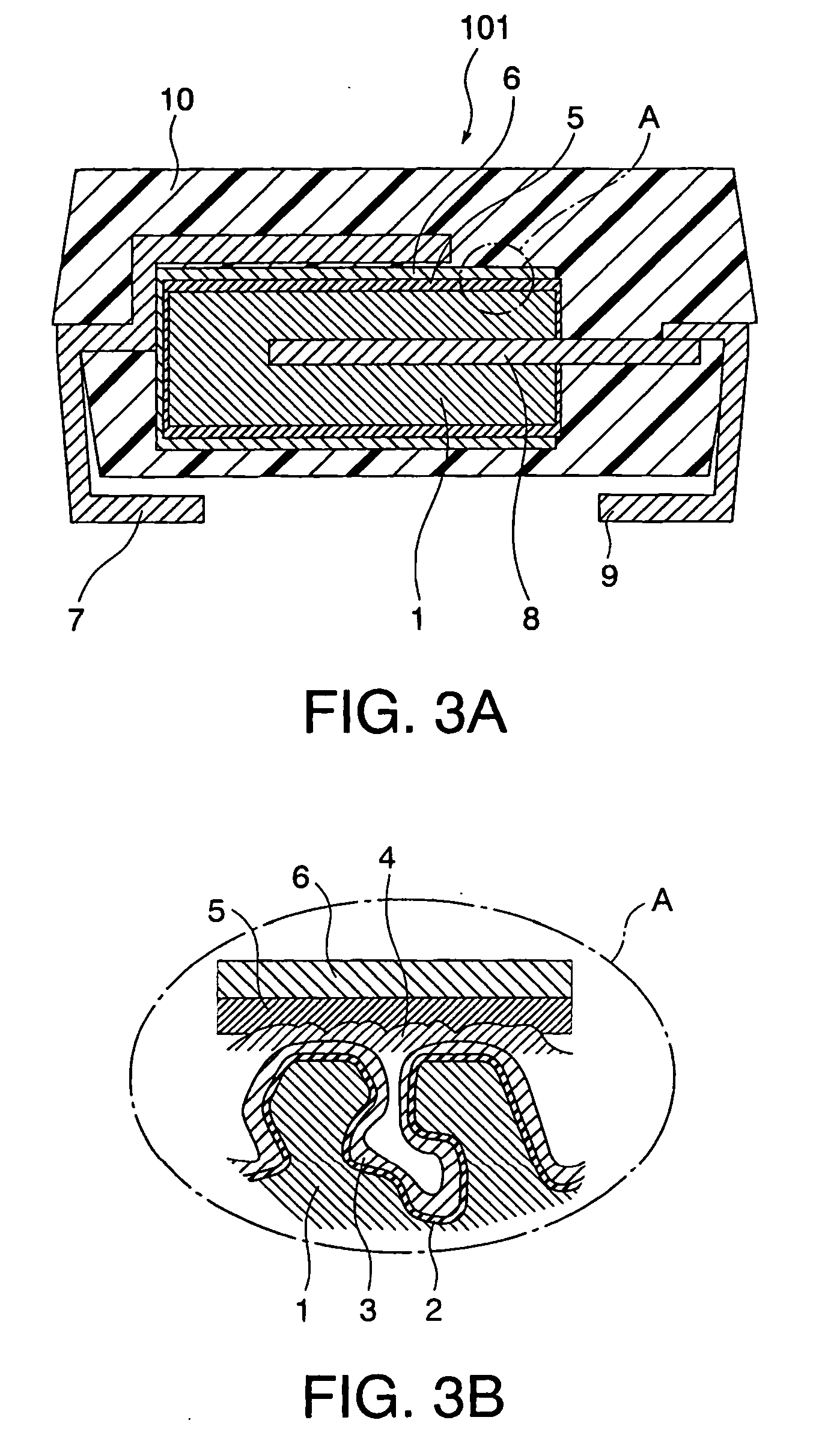
[0031] In Example 3 of this invention, a solid electrolytic capacitor 101 as shown in FIGS. 3A and 3B was produced by the use of the conductive polymer aqueous solution produced in Example 1.

[0032] Tantalum was used as a valve-acting metal for the solid electrolytic capacitor shown in FIG. 3A and, according to the known method described in patent document 5 or the like, a tantalum porous body 1 was produced from tantalum powder and an oxide film 2 was formed on the metal surface of the porous body 1 by anodic oxidation. By chemical oxidation polymerization using a pyrrole monomer and dodecylbenzene sulfonic acid iron, a polypyrrole conductive polymer layer 3 was formed, as a first solid electrolyte layer, on the oxide film 2 inside the tantalum porous body 1. In the example of patent document 5, a conductive polymer layer is then formed by electrolytic polymerization. However, in Example 3 of this invention, such a layer was formed by the use of the conductive polymer aqueous solut...


PUM

PropertyMeasurementUnit
weight ratioaaaaaaaaaa

Abstract

An electrically conductive polymer composition contains an electrically conductive polymer obtained by using a polymer in the form of cations composed of repeating structural units of 3,4-ethylene dioxythiophene and polystyrene sulfonic acid as anions and further contains naphthalene sulfonic acid as an additive. A solid electrolytic capacitor 101 or a surface-mount transmission line element 102 has a polypyrrole conductive polymer layer 3 as a first solid electrolyte and a poly(3,4-ethylene dioxythiophene) conductive polymer layer 4 as a second solid electrolyte.

Description

[0001] The present application claims priority to prior Japanese application JP 2005-44370, the disclosure of which is incorporated herein by reference. BACKGROUND OF THE INVENTION [0002] This invention relates to a solid electrolyte for use in a solid electrolytic capacitor and further relates to a solid electrolytic capacitor and a surface-mount transmission line element each using such a solid electrolyte. [0003] In recent years, a solid electrolytic capacitor has been developed which is obtained by forming a dielectric oxide film on a porous body of a valve-acting metal such as tantalum or aluminum by anodic oxidation and then forming on the oxide film an electrically conductive polymer layer as a solid electrolyte. Such solid electrolytic capacitors enable a reduction in equivalent series resistance (hereinafter referred to as “ESR”) as compared with a conventional capacitor using manganese dioxide as a solid electrolyte and thus has started to be used in various applications. ...

Claims


Application Information

Patent Timeline
Patent Type & Authority Applications(United States)
IPC IPC(8): H01G9/00
CPCH01G9/028H01G9/042H01G11/48Y10T29/41Y02E60/13Y10T29/417H01G11/56
Inventor TOIDA, SADAMUARAI, SHINJIARAKI, KENJIYOSHIDA, KATSUHIROASAMI, TADAMASASAITOU, TAKESHIMARUKO, YUUICHI
Owner TOKIN CORP
Learn More