Cylinder head assemblies

a technology of cylinder head and assembly, which is applied in the direction of cylinders, combustion engines, machines/engines, etc., can solve the problems of increasing the likelihood of engine knock, reducing the efficiency of overall engine performance, so as to improve the efficiency or horsepower of spark-ignited internal combustion engines, improve the efficiency or horsepower, and increase the efficiency of internal combustion engines.

Active Publication Date: 2006-08-31
LYCOMING ENGINES A DIV OF AVCO
View PDF17 Cites 7 Cited by
  • Summary
  • Abstract
  • Description
  • Claims
  • Application Information

AI Technical Summary

Benefits of technology

[0011] The present invention involves a combination of features that can contribute both to improved fuel efficiency and increased horsepower of a spark-ignited internal combustion engine. In a first embodiment of the present invention, a new original equipment manufacturer (“OEM”) engine with these features can improve efficiency or horsepower, e.g., by 10 percent, compared to conventional configurations. In a second embodiment of the present invention, an overhaul kit is disclosed to retrofit cylinder assemblies with these new features to achieve greater combustion efficiency and fuel savings while maintaining the safety and reliability of a certified engine. FAA regulations preclude certain increases in power on prior-rated systems. Therefore, while one type of overhaul kit for certified engines preferably addresses fuel efficiency in certified engines while maintaining certified status, the invention can also be conformed to an embodiment which increases power and performance in uncertified experimental engines.
[0012] The combination of several features as disclosed below produces a desirable result that can be used to boost power and improve efficiency as compared to engines having conventionally equipped cylinder head assemblies. A first feature of the present invention is an improved “squish” area that surrounds a valve region having a substantially “peanut-like” shape. The valve region may include first and second bulbous portions joined by a connecting region, or “waist.” The squish area and valve region may be formed by any suitable method, e.g., machining, into a relatively flat cylinder head. The squish area substantially surrounds the valve region and extends substantially around the perimeter of the piston crown. The result is the majority of combustion takes place in the relatively small area of the valve region within the combustion chamber.
[0013] A second feature of the present invention may include positioning two spark plugs at opposing sides of the waist of the valve region such that sparking is initiated in opposing directions within the peanut-shaped area of the combustion area. The positioning of the spark plugs encourages a short burn distance and rapid advancement of the flame front from opposite sides of the peanut-shaped combustion chamber.
[0014] A third feature of the present invention is modified intake and exhaust ports having improved airflow. Lowering the squish zone, compared to a conventional engine, slightly (e.g., a quarter inch) within the cylinder head structure lengthens the intake and exhaust ports, which increases the flow radius, permitting a more gradual sweep of the flowpaths within the ports. The sweeping flowpaths permit a greater volume of air to enter the intake valve without negatively impacting flow velocity or causing an adverse pressure as compared to the relatively “sharp” angles of conventional configurations.
[0015] In one embodiment, the intake port has been reconfigured as a “low-swirl” port to balance flow around the valve head. Conventional practice provides a port that biases flow to one side of the valve head producing a swirling motion in the mixture as it enters the combustion chamber. With a low-swirl port the mixture enters the combustion chamber evenly around the valve head reducing the rotational motion of the mixture in the cylinder.
[0016] In addition, an exhaust port that has been narrowed and reconfigured to provide an almost flat-bottomed “squat” passage in association with the improvements of the present invention has been found to further enhance performance. In essence, the floor of a conventional port is flattened, bulging the sides but narrowing the overall diameter of the passage. What had been an open space where exhaust would spin in turbulence has been made solid. The opportunity for this turbulence to form has been eliminated, and the gently sweeping curves now permit a more rapid exit of exhaust gas with relatively small residence time in the exhaust port and little transfer of energy from turbulence in the passage way. This passage would instinctively appear to let less gas through than a larger, more open port. However, it has been found that this flowpath shape actually improves the flow of the exhaust gas without having to increase the port's cross-sectional area.

Problems solved by technology

A poorly designed cylinder head may impede intake and exhaust gases from flowing optimally through the cylinder head, thereby causing flow losses and / or backpressure within the cylinder head and exhaust manifold.
But these techniques often result in increasing the likelihood of engine knock, which may significantly degrade overall engine performance.
If autoignition occurs before the piston reaches top dead center (“TDC”), the pressure wave will actually push against the piston during the compression stroke thereby reducing the available energy for the power stroke, and ultimately, reduce engine power.
Other conventional techniques to improve the efficiency and thoroughness of combustion in a cylinder head, such as increasing the compression ratio, off-center spark plug placement, and incorporation of slow-burn combustion chambers, can also lead to an increased likelihood of undesirable engine knock.
However, a faster burning chamber can impede the operation of other elements of the cylinder head.
While fuel enrichment provides a cooler running engine in that expansion or evaporation of excess fuel absorbs energy, fuel economy will suffer.
Another aspect of conventional cylinder heads that contribute to reduced efficiency and power output of a spark-ignited internal combustion engine is the method of airflow into, and out of, the cylinder head.
If either the intake or exhaust ports are not sized to accommodate the flow rates demanded by the engine, restricted airflow and decreased efficiency and power output of the engine will result.
However, enlargement of intake and exhaust ports are not without cost or impact on performance.

Method used


Image

  • Cylinder head assemblies
  • Cylinder head assemblies
  • Cylinder head assemblies

Examples


second embodiment

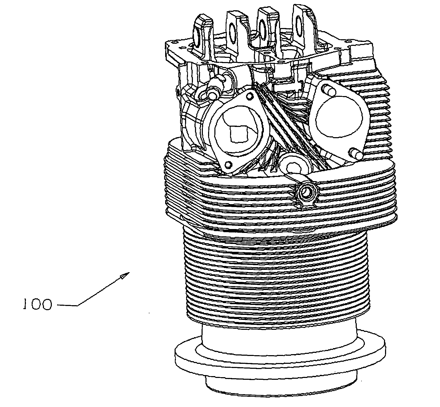
[0041] The present invention provides embodiments directed to improved cylinder head assemblies and associated methods. A first embodiment provides a new cylinder head assembly for an internal combustion engine. A second embodiment provides an overhaul kit for retrofitting an existing cylinder head assembly with the configurations of the present invention. A third embodiment provides a method of making an improved cylinder head assembly. The new cylinder head assembly and the overhaul kit of the present invention provide a spark-ignited internal combustion engine with greater fuel efficiency, reduced fuel octane requirement, and / or horsepower due to the combination of the following features.

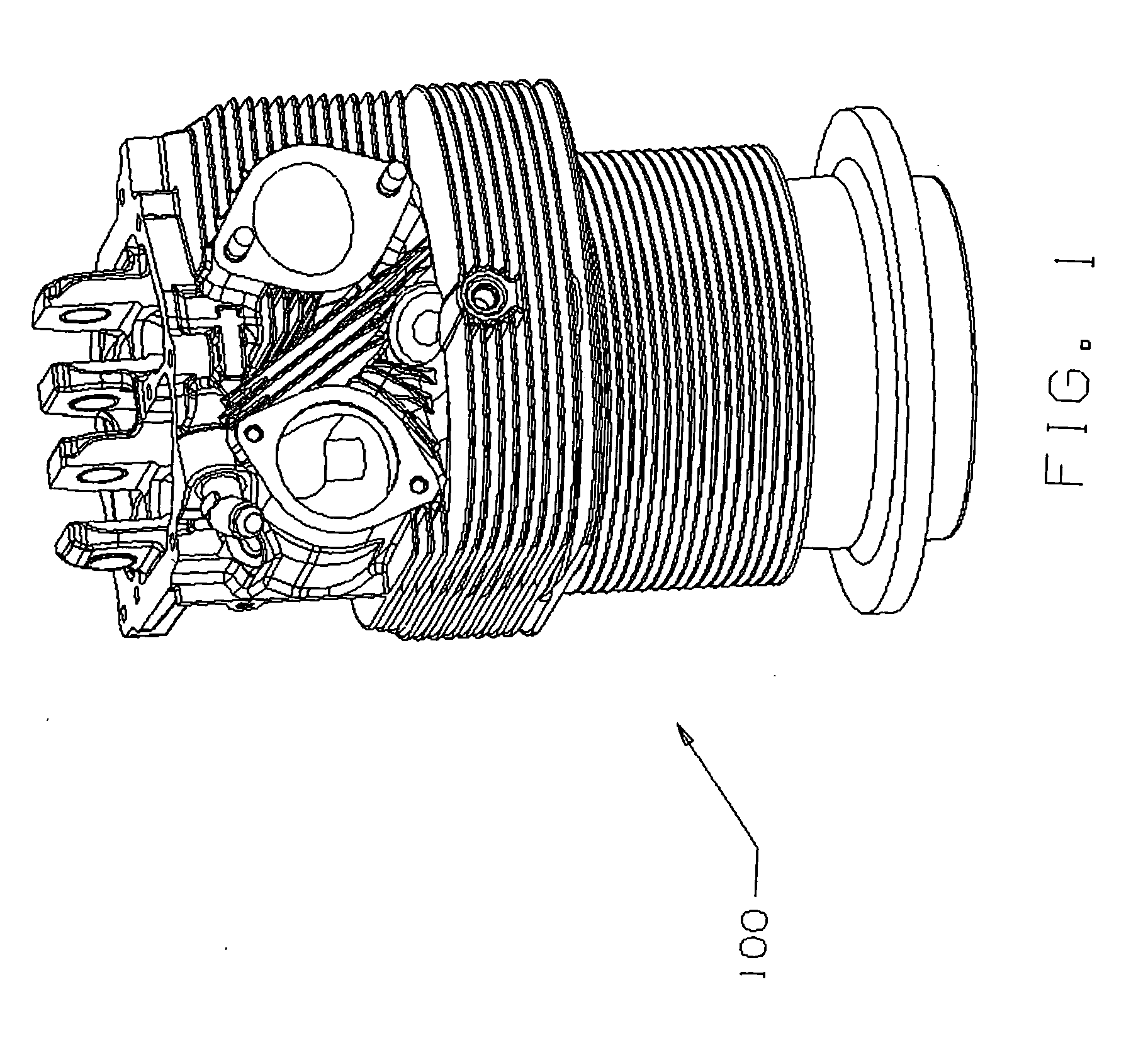
[0042] Referring to FIG. 1, a cylinder head 100 having the improved features of the present invention is shown. The features include, but are not limited to, an improved squish area, relocated spark plugs, and improved intake and exhaust flow.

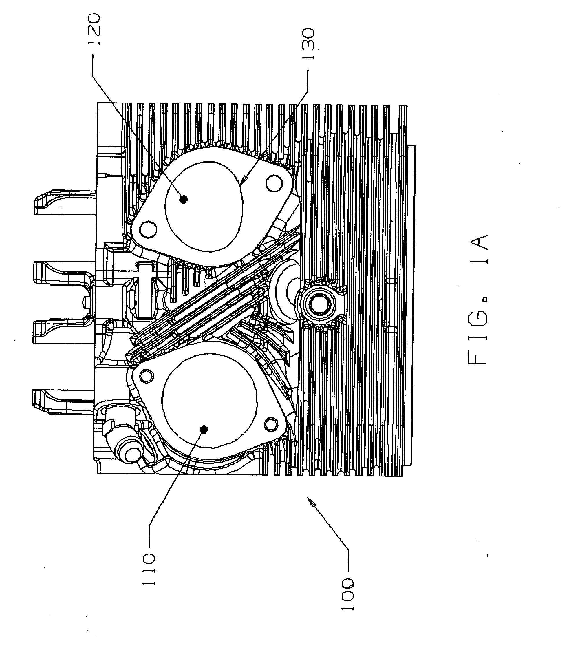
[0043] Referring to FIG. 1a, an exploded view of the ...


PUM


Abstract

Cylinder head assemblies including a cylinder head and a piston are disclosed. The cylinder head includes: a recessed valve region including a first and second bulbous portion connected by a waist, the first bulbous portion accommodating an intake valve and the second bulbous portion accommodating an exhaust valve; an intake port passageway having a gradually contoured flowpath between an intake port and the intake valve in the valve region; and an exhaust port passageway having a gradually contoured flowpath between an exhaust port and the exhaust valve in the valve region. The piston includes a recessed region that substantially conforms to the recessed valve region of the cylinder head. Related overhaul kits and methods of making improved cylinder head assemblies are further disclosed.

Description

[0001] This application includes material which is subject to copyright protection. The copyright owner has no objection to the facsimile reproduction by anyone of the patent disclosure, as it appears in the Patent and Trademark Office files or records, but otherwise reserves all copyright rights whatsoever. FIELD OF THE INVENTION [0002] The present invention relates generally to internal combustion engines and, more specifically, to reciprocating internal combustion engines used to power aircraft. BACKGROUND OF THE INVENTION [0003] There is continuous demand for higher efficiency and higher horsepower in aircraft internal combustion engines. Making an engine more efficient or more powerful is an exercise in compromise because a number of competing variables affect the performance of an engine. [0004] For example, the efficiency and power output of a spark-ignited internal combustion engine are directly affected by both the timing of the spark and the compression characteristics in ...

Claims


Application Information

Patent Timeline
Patent Type & Authority Applications(United States)
IPC IPC(8): F02F1/42F02F3/00F02B23/00
CPCF02B23/08F02B2023/085F02F1/06F02F1/30Y02T10/125Y02T10/146Y02T10/12
Inventor MATAS, SCOTTMOONEY, TIMSITAR, MIKE
Owner LYCOMING ENGINES A DIV OF AVCO
Why Eureka
Try Eureka