
Method and apparatus for controlling microfluidic flow

a microfluidic and flow control technology, applied in the field of microfluidic flow control, can solve the problems of limited precision/range, high cost of miniature pressure sensors, and limited control of open loop, and achieve the effects of simple and cheaper, price, range and precision, and easy integration

Inactive Publication Date: 2006-08-31
BROWN UNIVERSITY
View PDF9 Cites 16 Cited by
  • Summary
  • Abstract
  • Description
  • Claims
  • Application Information

AI Technical Summary

Benefits of technology

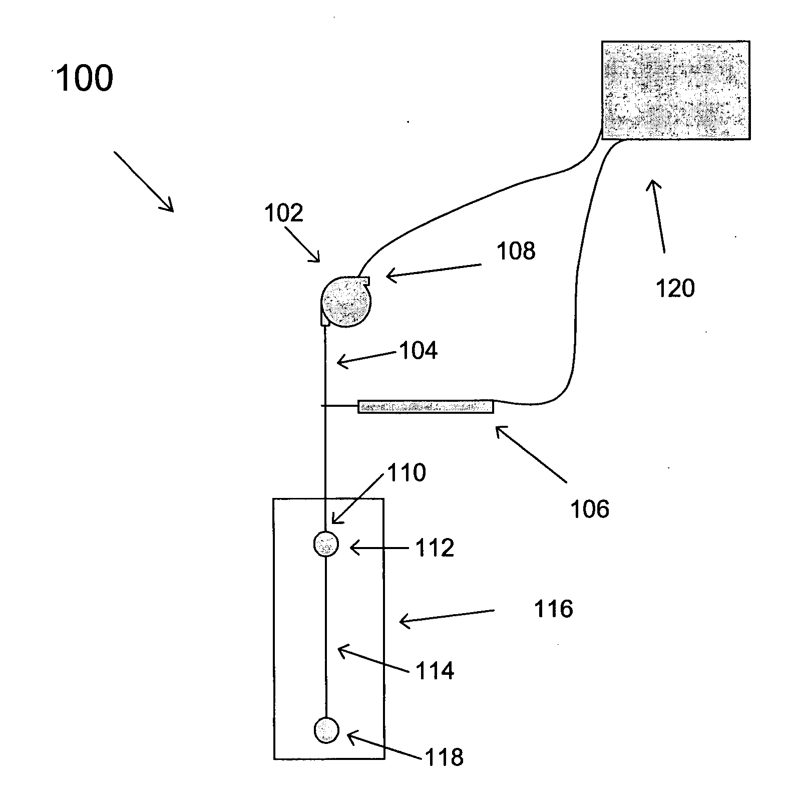
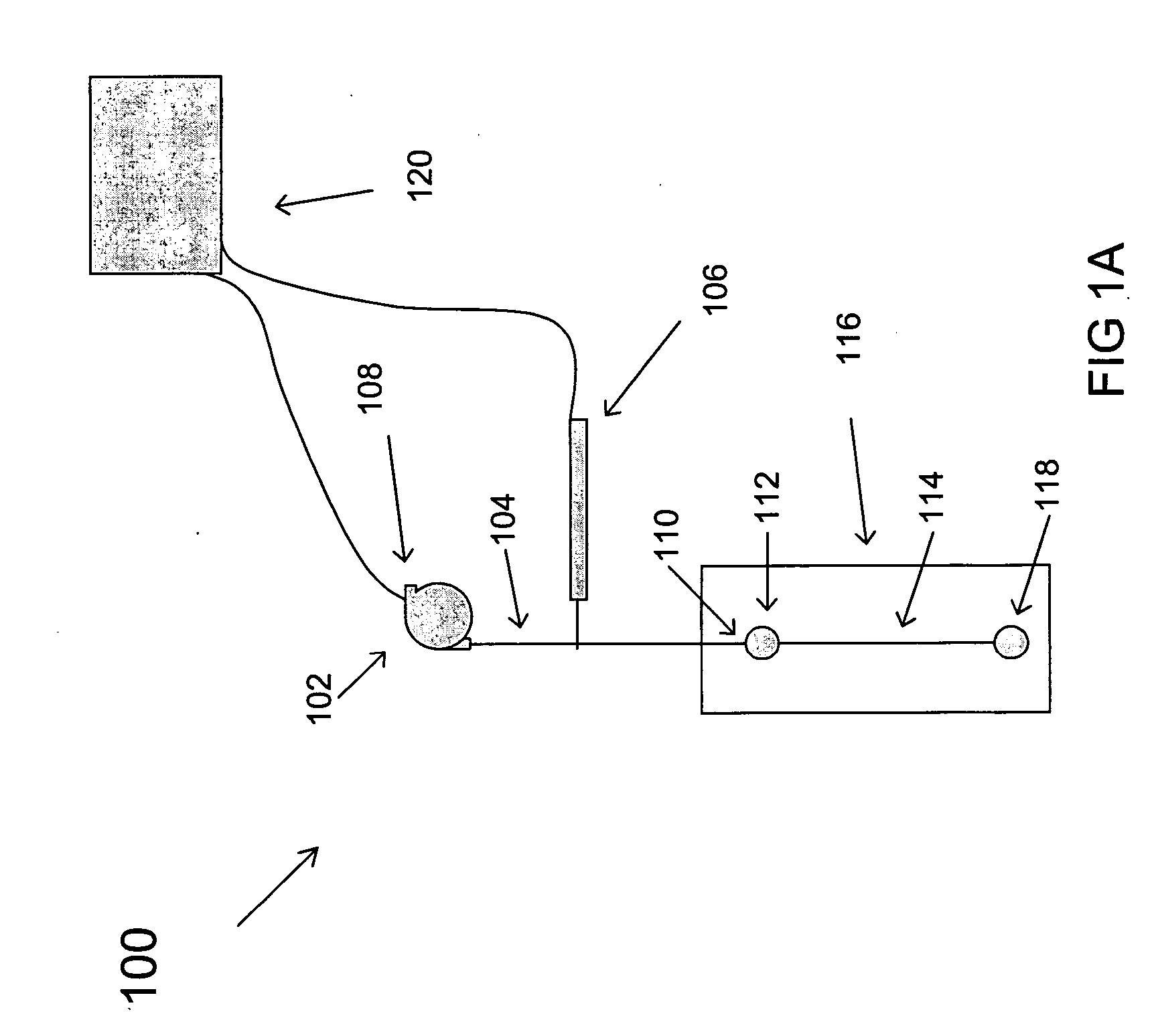
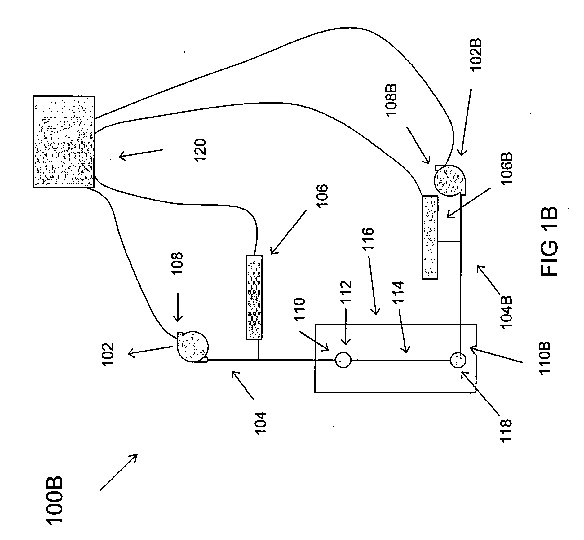
[0023] The disclosed pressure control method and apparatus has several advantages. For example, in the disclosed pressure control method and apparatus, the pressures can be set by an analog control signal, allowing a number of pressure channels to be arranged in parallel. Also, the disclosed pressure control by nature can determine precise pressure at each channel, without the need for further equipment. The disclosed pressure control method and apparatus, being adaptable to analog control, can be adapted without any inherent pressure resolution limit by adjusting the feedback gain and choosing an appropriate gearing for the pump motor, in contrast to the inherent step size limit in syringe systems built with stepper motors. Thus, the resolution of the system is typically finer than the accuracy of the sensor, and thus pressure resolution typically is constrained only by the resolution and stability of the gas pressure sensor employed. Because the gas pressure sensor can be a macroscopic gas pressure sensor, many more options in price, range and precision can be available compared to special purpose miniature sensors. Also, it can be much easier to integrate off-chip pressure sensors, e.g., macroscopic gas pressure sensors into the disclosed pressure control than to embed a miniature gas pressure sensor in a microfluidics chip. Moreover, as shown in Example 1, pressure control can be achieved to better than the rated resolution of the pressure sensor. Further, the disclosed pressure control method and apparatus can also be employed with a passive channel for monitoring pressure. The disclosed pressure controller can be assembled from components that are generally simpler and cheaper than typical syringe pumps and their control systems. The disclosed pressure control method and apparatus can also be more compact and more easily networked than a comparable syringe pump system, especially for multi-channel systems.
[0024] The disclosed electrical control method and apparatus can provide closed loop control that can lead to more precise control in constant-current and constant-voltage modes, which can be chosen independently for each electrical channel. In either mode, continuous measurements of voltage and current can be made. Another feature is that the disclosed electrical control can be employed in combination with available programmable high voltage supplies, whereas previously such supplies were generally inadequate for microfluidics, for example because of the lack of precise current measurement capability.

Problems solved by technology

However, such programmable syringe pumps typically offer only open loop control without means to readily measure pressure differentials across the microfluidic features of the chip.
However, compared to the wide range of macroscopic pressure sensors available, such miniature pressure sensors can be expensive, limited in precision / range and difficult to integrate into microfluidic chips.
Moreover, syringe pump platforms can be difficult to adapt to multi-channel arrangements.
Also, operation and maintenance of a multiple syringe pump system can be labor intensive.
Moreover, dealing with several such high voltage electrical channels can present a challenge to measurement of an electrical channel's output current.
A conventional low-side current measurement can be impossible because a microfluidic chip typically has no common drain.
Also, non-contact “clamp” style current measurements typically would not be effective with direct currents in the microampere range.
Moreover, precise control of current and fluid transport can be difficult when employing high voltage supplies.
Although many basic regulated programmable high voltage power supplies are available, they are not typically useable in a microfluidics application without modifications or external measurement setups.
One reason for this is that many high voltage supplies are unable to sink current, which is generally not acceptable in a microfluidics chip where electrical channels can be directly interacting through the chip.
Another reason is that available high voltage supplies typically either have relatively coarse current monitoring or lack current monitoring altogether.
Commercially available electrical microfluidic controllers can be effective in some respects, but typically can be difficult or impossible to integrate with pressure control, which can be desirable for many experimental reasons (for example, for easily switching between fluids of widely different conductivities).
Moreover, many otherwise capable commercial controllers are not equipped to easily integrate with other typical lab instrumentation such as pressure controllers, heaters, spectroscopic detectors, microscopes, or the like.

Method used


Image

  • Method and apparatus for controlling microfluidic flow
  • Method and apparatus for controlling microfluidic flow
  • Method and apparatus for controlling microfluidic flow

Examples


example 1

Pressure Controller

[0051] A pressure controller was built according to the disclosed pressure controller. By appropriate selection of components, eight pressure channels were combined with a 15 PSI differential gas pressure sensor with an accuracy of + / −0.015 PSI. The accuracy and range can depend on the gas pressure sensor chosen, but in this example the pressure was found to be regulated to within better than 0.067% of the gas pressure sensor output. In this system, target pressures were reached well within one second.

[0052] A portion of the control electronics was dedicated to getting an accurate pressure measurement. A silicon piezo-resistive differential gas pressure sensor received constant current excitation and its output was calibrated for gain and zero offset. The output gain was set at 0.333 volts / pounds per square inch (V / PSI, e.g., 0.9 PSI air pressure corresponds to 0.3 V signal and −0.9 PSI air pressure corresponds to −0.3 V signal).

[0053]FIG. 6 is a graph of press...

example 2

Electrical Controller

[0063] Example 2 demonstrates one electrical channel of a prototype 8 electrical channel 0-5000 V controller that can support constant voltage or constant current modes to an accuracy of within 0.1 microamperes.

[0064] For each electrical channel, a commercially available programmable voltage supply was employed that was capable of 0-5000 V at 200 microamperes. The output of each supply enters the disclosed electrical control network which can calculate the output voltage and current and which can be connected via an output to an electrode contacting a conduit in a microfluidic chip.

[0065] In this example, two electrical channels were connected to each other through a 100 megaohm resistor, so that, for example, a 500 V difference between the electrical channels can result in one electrical channel sourcing 5 microamperes and the other electrical channel sinking 5 microamperes.

[0066] One electrical channel was held at 2000 V while the other electrical channel ...

example 3

Computer and Software Control

[0070] The pressure and electrical controllers can interact with the microfluidic chip through analog voltage signals, producing measurements and responding to input stimuli in terms of voltages. Thus, a desirable computer control system can work with analog voltages as well. An exemplary setup (employed in Examples 1 and 2) can be driven by a single desktop computer which can be equipped with appropriate analog inputs, outputs, and control software. Using commercially available components (e.g., a 32 channel 13 bit analog output card and two 16 channel 16 bit analog input cards, controlled by LabView software from National Instruments, Austin Tex.; In other embodiments, custom components can be employed, e.g., dedicated analog inputs and outputs, custom software programming), real-time graphical monitoring of all channels was achieved. Moreover, these values were recorded, and could be correlated with the output of other instruments or used to control ...


PUM


Abstract

An apparatus includes a pump; a gas pressure sensor; a microfluidic chip defining a microfluidic conduit; and a gas conduit providing fluid communication between the pump, the gas sensor and the microfluidic conduit; and a controller coupled to the pump and the gas pressure sensor, whereby the controller controls the pump, thereby controlling the gas pressure at the microfluidic conduit. An apparatus includes a microfluidic chip defining a microfluidic conduit extending from a microfluidic source electrode to a microfluidic ground electrode; a first resistor coupled to the microfluidic source electrode; a first and a second voltage divider, the first divider coupling a first power ground to a side of the first resistor opposite the microfluidic chip, the second divider coupling a second power ground to the lead between the first resistor and the microfluidic source electrode, and a first voltage sensor; and a second voltage sensor. Also included are methods of operating the apparatus.

Description

RELATED APPLICATION [0001] This application claims the benefit of U.S. Provisional Application No. 60 / 656,237, filed on Feb. 25, 2005 the entire teachings of which are incorporated herein by reference.BACKGROUND OF THE INVENTION [0002] One goal of microfluidics is to provide precise, automated fluid processing on minimally sized samples. A key part of a microfluidic platform is the control instrumentation which manipulates the fluid samples in the microfluidic features (e.g., conduits and wells) of the microfluidic chip. Typically, fluid can be transported through the microfluidic features by an electrical or pressure gradient. [0003] Pressure-controlled fluid transport has been typically achieved with programmable syringe pumps, usually driven by stepper motors. Sample fluid can be loaded into a syringe pump and the output routed directly into a microfluidics chip. The syringe can be operated to create a pressure differential on the fluid, transporting it through the microfluidic c...

Claims


Application Information

Patent Timeline
Patent Type & Authority Applications(United States)
IPC IPC(8): F04B49/06
CPCB01L3/0293B01L3/5027B01L2200/143B01L2200/146B01L2300/14B01L2400/0415B01L2400/0481B01L2400/0487G01N35/1016G01N2035/1039
Inventor ROSENSTEIN, JACOBTRIPATHI, ANUBHAV
Owner BROWN UNIVERSITY
Learn More