Laser surface treatment

Active Publication Date: 2006-09-28
MATSUSHITA ELECTRIC WORKS LTD +1
View PDF16 Cites 17 Cited by
  • Summary
  • Abstract
  • Description
  • Claims
  • Application Information

AI Technical Summary

Benefits of technology

[0006] Therefore, a primary concern of the present invention is to provide a laser surface treatment for forming a fine periodic structure that is effective

Problems solved by technology

In this case, however, there is an inconvenience that the positional adjustment of an optical system must be performed with high accuracy such that the two femtosecond-pulse laser beams are interfered to each other.
In addition, there is a problem that a large area treatment is difficul

Method used


Image

  • Laser surface treatment
  • Laser surface treatment
  • Laser surface treatment

Examples


Example

EXAMPLES 1 to 12

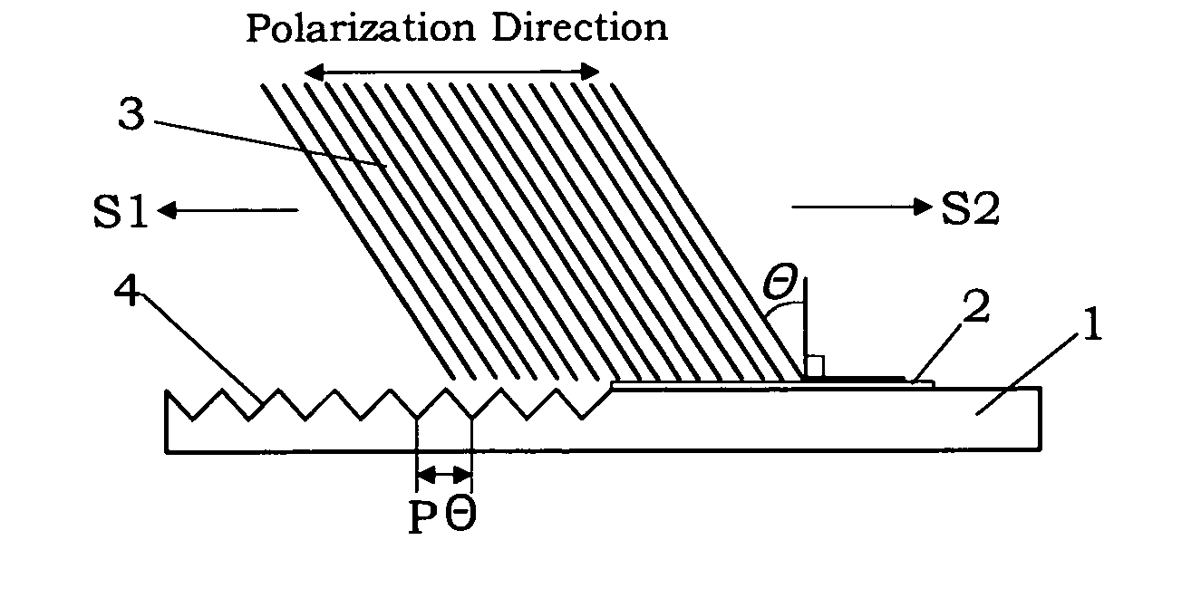
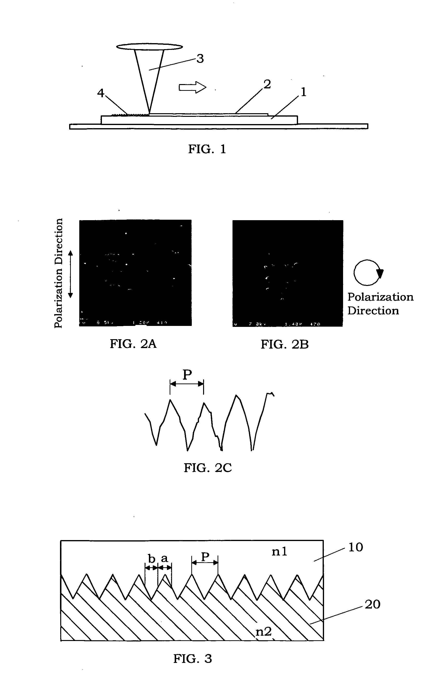
[0038] In each of Examples 1 to 12, the following laser surface treatment was performed. That is, a sapphire single crystal was used as the substrate. A cupper film was formed on the substrate by a conventional sputtering method to have the thickness listed in Table 1. Then, as shown in FIG. 1, the copper film was removed from the substrate by irradiation of an ultra-intense short-pulse laser beam having a pulse width of 100 fs under a reduce pressure of 0.01 Pa with the laser energy density listed in Table 1. A periodic interval of a resultant fine periodic structure was measured by using scanning electron microscope (SEM). Results are shown in Table 1. In addition, SEM photographs of the fine periodic structures formed in Examples 3, 6, 9 and 12 are shown in FIGS. 6A to 6D. The laser beam used in these Examples is a linearly-polarized laser. Therefore, the fine periodic structure has fine elongate asperities extending in a direction perpendicular to the polarizati...

Example

[0039] In Examples 13, a copper film is formed on a fused silica substrate, and then the copper film is removed from the substrate by irradiation of an ultra-intense short-pulse laser beam having a pulse width of 100 fs, which is a linearly-polarized laser beam. Similarly, the fine periodic structure of Example 14 was formed on the fused silica substrate by substantially the same procedures as Example 13 except for using a circularly-polarized laser beam. In these cases, a periodic interval of a resultant fine periodic structure is approximately 200 nm.

[0040] With respect to each of Examples 13 and 14, the transmission factor of the fused silica substrate was measured by use of two lights having wavelengths of 670 nm and 450 nm. In addition, the transmission factor of the fused silica substrate without the laser surface treatment was also measured as Comparative Example 1. Results are shown in Table 2. It can be understood from the results of Table 2 that the laser surface treatmen...


PUM

PropertyMeasurementUnit
Timeaaaaaaaaaa
Timeaaaaaaaaaa
Thicknessaaaaaaaaaa

Abstract

A laser surface treatment for reducing reflection loss on the surface of an optical material is provided. A metal film is formed on the surface of the optical material, and then the metal film is removed from the optical material by irradiation of an ultra-intense short-pulse laser beam having a pulse width of 1 femtosecond to 100 picoseconds, so that a fine periodic structure is formed on the surface of the optical material exposed by the removal of the metal film. The obtained fine periodic structure has asperities with a periodic interval of preferably 50 to 1000 nm, which can be controlled by changing the laser energy density.

Description

BACKGROUND OF THE INVENTION [0001] 1. Field of the Invention [0002] The present invention relates to a laser surface treatment using an ultra-intense short-pulse laser beam, and particularly for forming a fine periodic structure, which is effective to reduce reflection loss on the surface of an optical material. [0003] 2. Disclosure of the Prior Art [0004] As a technique of forming a fine periodic structure on a surface of transparent substrate by use of a laser beam, for example, Japanese Patent Early Publication [KOKAI] 2003-57422 discloses a method of forming a periodic microstructure by irradiation of femtosecond-pulse laser beams. This method is essential to use two femtosecond-pulse laser beams interfered with each other, which are irradiated to a substrate to form a hologram diffraction grating on the substrate. The obtained diffraction grating has a periodic structure with a minimum average size of 5 to 200 nm. In this case, however, there is an inconvenience that the positi...

Claims


Application Information

Patent Timeline
IPC IPC(8): B23K26/36
CPCG02B1/11G02B1/118G02B1/12G02B1/111H01S3/00C23C16/483
Inventor TANAKA, KENICHIROFUJITA, MASAYUKI
Owner MATSUSHITA ELECTRIC WORKS LTD
Why Eureka
Try Eureka