Exhaust gas purification catalyst

a technology of exhaust gas and catalyst, which is applied in the direction of physical/chemical process catalyst, metal/metal-oxide/metal-hydroxide catalyst, separation process, etc., can solve the problems of deteriorating catalytic conversion performance, affecting the efficiency of catalytic conversion, and affecting the conversion efficiency of catalytic reactions, etc., to achieve excellent oxidation condition, increase the number of active sites, and high activity

Inactive Publication Date: 2006-09-28
TOKYO ROKI +1
View PDF11 Cites 72 Cited by
  • Summary
  • Abstract
  • Description
  • Claims
  • Application Information

AI Technical Summary

Benefits of technology

[0013] Therefore, an object of the present invention is to provide a catalyst having improved catalytic conversion performance and excellent thermal resistance in consideration of the specific surface area and surface condition of alumina carrying catalytic precious metal.
[0097] In the eighteenth solution, since palladium is distributively carried on the particulate alumina and the particulate oxygen storage component, this increases the number of active sites for palladium and provides high activity particularly for conversion of hydrocarbon and carbon monoxide. Further, palladium can be controlled into an excellent oxidation condition by active oxygen supplied from the particulate oxygen storage component, thereby enhancing the efficiencies of palladium converting hydrocarbon and carbon monoxide by oxidation over a long period of time.

Problems solved by technology

If, however, the catalyst is placed close to or comparatively close to the engine, it will be exposed to extremely high-temperature exhaust gas during acceleration operation and other operations of the engine.
This results in a problem that particles of catalytic precious metals, such as platinum (Pt), rhodium (Rh) and palladium (Pd), carried on alumina or an oxygen storage component in a catalytic coating move on the surface of the alumina or the oxygen storage component to coagulate and cause sintering, resulting in deteriorated conversion performance.
In particular, if different kinds of catalytic precious metals sinter and alloy together, they will loose catalytic activity and thereby significantly deteriorate their catalytic conversion performance, which is a big problem.
If support materials bond together, i.e., different kinds of aluminas or alumina and oxygen storage component bond to each other to sinter, a problem arises that catalytic precious metal particles are buried inward of the surface of the sintered support material to further deteriorate the catalyst.
However, when the specific surface area of alumina is large, it can be considered that even if support materials sinter, the loss of catalytic precious metal due to burial in the sintered support material is small and, therefore, deterioration in conversion performance is small.
However, as results of inventors' research and development of catalysts excellent in thermal resistance, they have found that when different kinds of catalytic precious metals including platinum, rhodium and palladium are individually carried on alumina particles of the same kind having the same specific surface area and the same basicity, a deterioration in conversion performance has been observed even if the alumina particles have a large specific surface area and a high basicity.
Therefore, interaction is not sufficiently established between each catalytic precious metal and its support material such as alumina or oxygen storage component and it cannot necessarily be said that the surface state of each catalytic precious metal is optimized for exhaust gas purification.
Furthermore, it cannot be said that the dispersity of each catalytic precious metal over the support material is high.
Therefore, there is a problem that when the catalyst is exposed to high-temperature exhaust gas, each catalytic precious metal may sinter and not sufficiently exhibit its catalytic property, resulting in deteriorated exhaust gas purification performance of the catalyst.
Furthermore, if sintering occurs between different kinds of aluminas or between different kinds of oxygen storage components, catalytic precious metals are buried inward of the surfaces of the support materials to further deteriorate the catalyst.
Any proposal of in which distribution ratio the same kind of catalytic precious metal should been carried on alumina and the oxygen storage component, however, has not up to now been made.
If, however, the amount of ZrO2 added is increased, the content of cerium dioxide in the mixed oxide is correspondingly decreased so that the mixed oxide deteriorates its oxygen storage capacity, resulting in deteriorated conversion performance of the catalyst.

Method used


Image

  • Exhaust gas purification catalyst
  • Exhaust gas purification catalyst
  • Exhaust gas purification catalyst

Examples


embodiment i

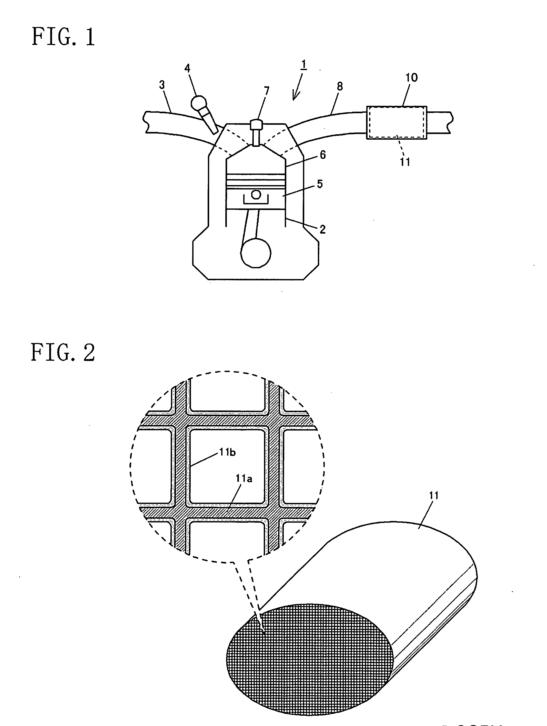
[0127]FIG. 1 shows a schematic structure of an automobile spark ignition engine 1 at which a three-way catalyst 11 according to this embodiment is mounted. Specifically, the engine 1 has a plurality of air cylinders 2 (only one shown in the figure) and is configured so that an air-fuel mixture of air supplied through an intake passage 3 and fuel supplied by a fuel injection valve 4 is explosively combusted in a combustion chamber 6 by spark ignition of an ignition plug 7 and the resultant exhaust gas is released to the air through an exhaust passage 8. The exhaust passage 8 is provided with a catalytic converter 10 and the three-way catalyst 11 according to the present invention is contained in the catalytic converter 10. The catalytic converter 10 is disposed in an upstream part of the exhaust passage 8 as much as possible, as by directly coupling it to the convergence of an exhaust manifold, in order to attain high conversion efficiency from just after start-up of the engine 1. As...

example 1

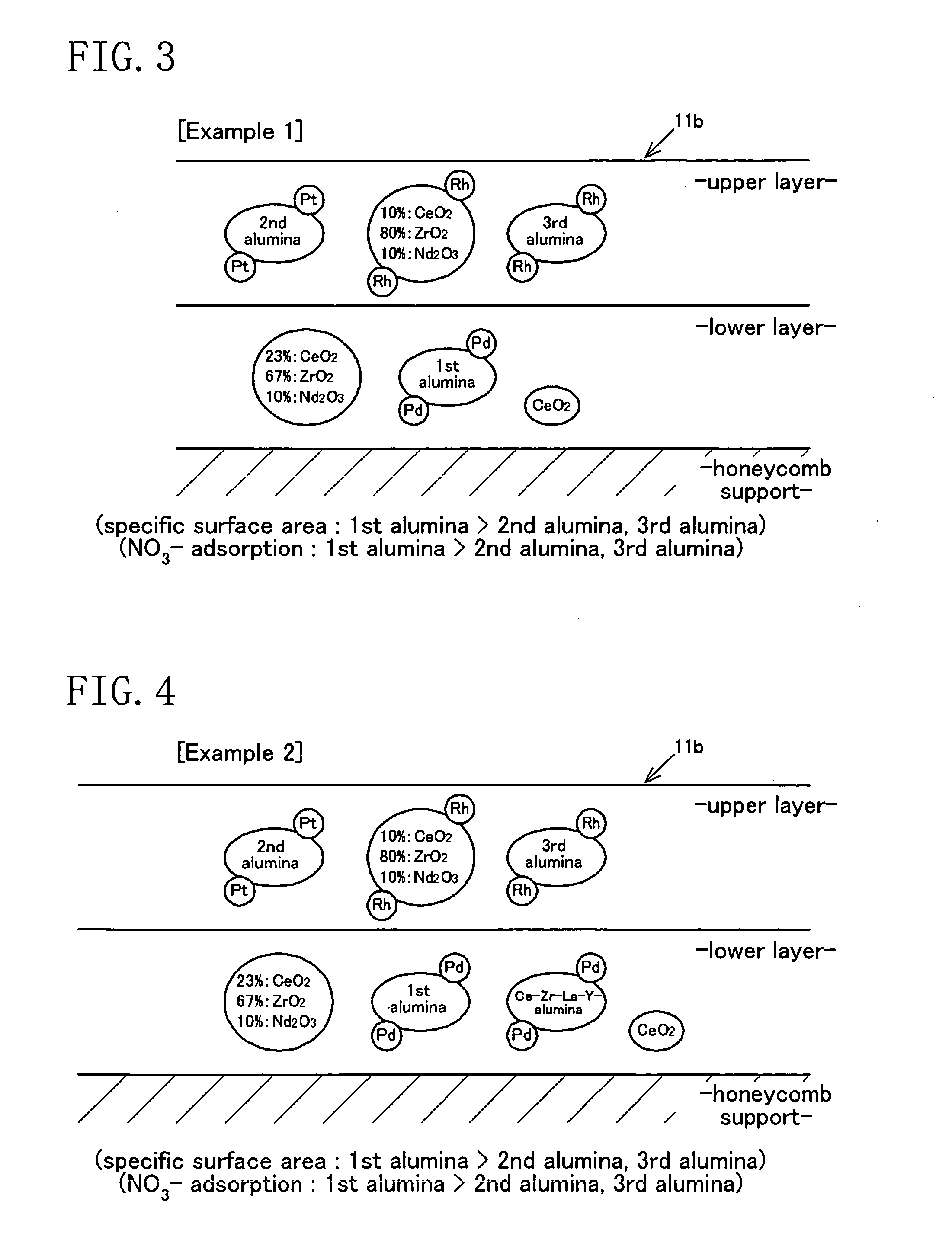
[0146] A three-way catalyst has two catalytic layers, upper and lower, as shown in FIG. 3 (see FIG. 9).

-Lower Catalytic Layer-

[0147] Ce—Zr—Nd mixed oxide: carried amount of 5.7 g / L

[0148] Pd / first alumina: carried amount of 50.0 g / L (Pd: carried amount of 0.7 g / L)

[0149] cerium dioxide: carried amount of 5.7 g / L

[0150] zirconia binder: carried amount of 8.5 g / L

-Upper Catalytic Layer-

[0151] Pt / second alumina: carried amount of 25.5 g / L (Pt: carried amount of 0.08 g / L)

[0152] Rh / Ce—Zr—Nd mixed oxide: carried amount of 56.0 g / L (Rh: carried amount of 0.1 g / L)

[0153] Rh / third alumina: carried amount of 17.0 g / L (Rh: carried amount of 0.04 g / L)

[0154] zirconia binder: carried amount of 11.0 g / L

[0155] The mass ratio expressed by ZrO2 / (CeO2+ZrO2+Nd2O3) in the Ce—Zr—Nd mixed oxide is 80 mass % for the upper layer and 67 mass % for the lower layer.

example 2

[0156] In the three-way catalyst as in Example 1, the lower catalytic layer further contains a Pd-carried Ce—Zr—La—Y-alumina compound at a carried amount of 25.0 g / L (of which the carried amount of Pd is 0.35 g / L) and the other components are the same as those in Example 1 (see FIGS. 9 and 10).

[0157] As shown in FIG. 11, in Example 2, the amounts of Pd carried per unit mass on the first alumina and the Ce—Zr—La—Y-alumina compound in the lower layer are A=0.70 / 50.0 and B=0.35 / 25.0, respectively, and therefore the relation A=B holds.

[0158] Further, the amounts of Rh carried per unit specific surface area (SSA) on the third alumina and the Ce—Zr—Nd mixed oxide in the upper layer are C=0.04 / 78 and D=0.10 / 17, respectively, and therefore the relation C


PUM

PropertyMeasurementUnit
temperatureaaaaaaaaaa
lengthaaaaaaaaaa

Abstract

In an exhaust gas purification catalyst in which a catalytic coating containing plural kinds of aluminas and plural kinds of oxygen storage components each carrying a catalytic precious metal is coated on a honeycomb support, the catalytic coating is formed of an upper layer and a lower layer, palladium is carried on a first alumina and a Ce—Zr—La—Y-alumina compound having oxygen storage capacity in the lower layer, platinum is carried on a second alumina in the upper layer, and rhodium is carried on a third alumina and a Ce—Zr—Nd mixed oxide having oxygen storage capacity in the upper layer.

Description

CROSS-REFERENCES TO RELATED APPLICATIONS [0001] This application claims priority under 35 USC 119 to Japanese Patent Applications Nos. 2005-85515, 2005-85516, 2005-85517, 2005-85518 and 2006-5263, the entire contents of all of which are incorporated herein by reference. BACKGROUND OF THE INVENTION [0002] (a) Field of the Invention [0003] This invention relates to exhaust gas purification catalysts and pertains to the technical field of exhaust gas purification for automobiles. [0004] (b) Description of the Related Art [0005] Three-way catalysts are conventionally known which can concurrently convert hydrocarbon (HC), carbon monoxide (CO) and nitrogen oxides (NOx) contained in exhaust gas from automobiles into carbon dioxide (CO2), water (H2O) and nitrogen (N2). There has recently been a demand for a three-way catalyst of such kind to attain high conversion efficiencies of all three pollutants from just after engine start. To satisfy this demand, a technique is employed which increas...

Claims


Application Information

Patent Timeline
Patent Type & Authority Applications(United States)
IPC IPC(8): B01J23/10
CPCB01D53/945B01J23/04B01J23/10B01J23/63B01J35/0006B01J37/0244B01J37/0248Y02T10/22Y02T10/12
Inventor KAWAMOTO, TOMOHIKOFUJITA, KATSUYUKITOKUYAMA, TADASHIKAWABATA, HISAYASHIGETSU, MASAHIKOAKAMINE, MASAAKITAKAMI, AKIHIDE
Owner TOKYO ROKI
Why Eureka
Try Eureka