
Process for pipe seal manufacture

a technology of annular member and pipe seal, which is applied in the field of process for forming annular member, can solve the problems of substandard seal performance, large diameter of seal, less than 12 inch diameter, etc., and achieves the effect of improving the quality of spliced joints, avoiding time or energy expenditure, and improving performan

Active Publication Date: 2006-10-05
CELANESE INT CORP
View PDF35 Cites 10 Cited by
  • Summary
  • Abstract
  • Description
  • Claims
  • Application Information

AI Technical Summary

Benefits of technology

[0011] One advantage of exemplary forms of the present invention is that enhanced performance TPVs can replace TSRs to form large diameter pipe seals.
[0012] Another advantage of exemplary embodiments is that the splicing operation is completed without the time or energy expenditures required in vulcanization of TSRs.
[0013] Another advantage of exemplary embodiments is that the quality of the spliced joint is improved as compared to heat welding because the operation is performed on the molten TPV prior to significant cooling. The joints may exhibit superior strength and minimal flashing as compared to standard hot plate welding on TPVs.
[0014] Another advantage of exemplary embodiments is the reduced tooling and equipment costs as compared to an injection molding process. For example, one extrusion die may be capable of producing seals for several sizes of pipe.

Problems solved by technology

The softer grades of TPVs do not always heat weld in a welding process with adequate strength as compared to a vulcanized splice in a TSR.
In addition, the joint or weld, can provide a leak path both during pressure and vacuum testing of the piping system and its subsequent use if the weld joint is not effective.
However, seals having large diameters (e.g., greater than 12 inch diameter) or with lower unit volume are not typically suitable for injection molding processes due to high tooling and equipment costs.
In the thermal welding process excess thermoplastic extends upon joining of the ends thus causing leaking or substandard seal performance.
Thus, the heat-welded joint of thermoplastic, particularly thermoplastic elastomer, has substandard performance with respect to the thermoset rubber seals that utilize a vulcanized splice with little excess.
Thus TPE seals have been inadequate for more demanding applications such as sewer pipes due to weld quality and long-term performance.

Method used


Image

  • Process for pipe seal manufacture
  • Process for pipe seal manufacture
  • Process for pipe seal manufacture

Examples


Embodiment Construction

Definitions

[0024] Thermoplastic Elastomer (TPE): a diverse family of rubber like materials that, unlike conventional vulcanized rubbers, can be processed and recycled like thermoplastic materials. Typical examples include blends of “hard” crystalline, semi-crystalline, or glassy polymers (for instance those having a Tm greater than about 110° C. or Tg greater than about 60° C., as measured by differential scanning calorimetry (DSC), more preferably with amorphous or low-crystallinity polymers (Tm less than about 90° C. or Tg less than 60° C. by DSC). Examples of hard polymers include the non-polar and polar engineering resins such as polypropylene, polyethylene, polyamide, polycarbonate, and polyester resins. The “soft” polymers include most rubbers, particularly the non-polar olefin rubbers, for hard polyolefins, and polar rubbers for polar hard resins. Non-polar rubbers include ethylene-propylene rubber, very low density polyethylene copolymers comprising C4 to C8 α-olefin or vi...


PUM

PropertyMeasurementUnit
Angleaaaaaaaaaa
Diameteraaaaaaaaaa
Temperatureaaaaaaaaaa

Abstract

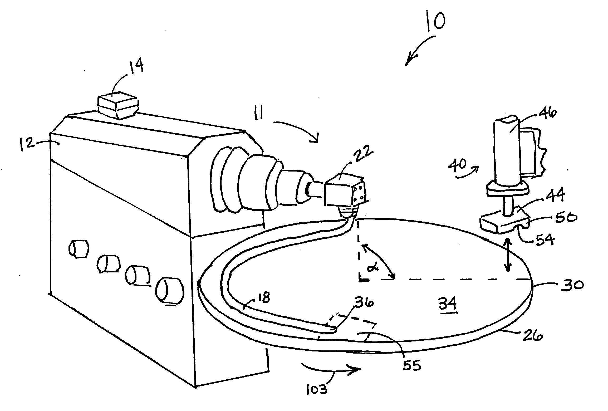
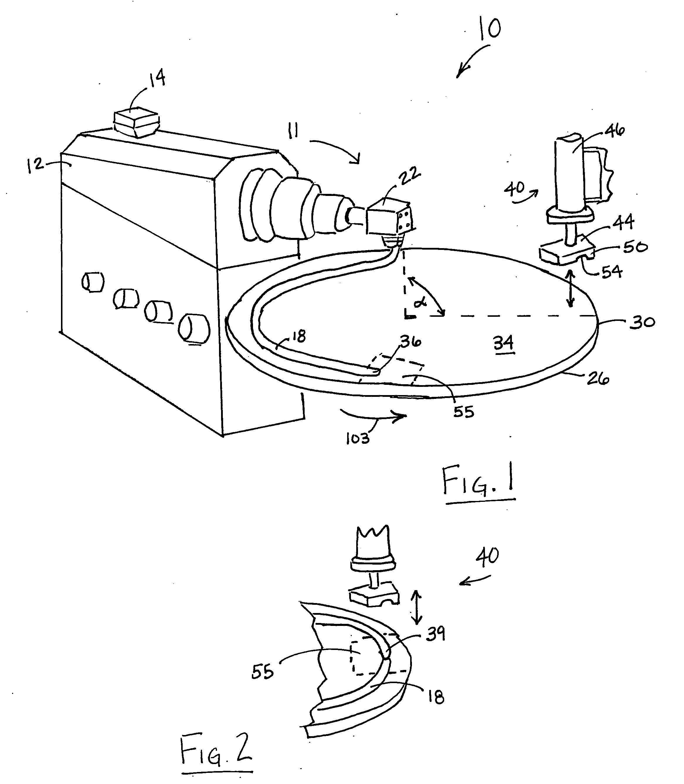
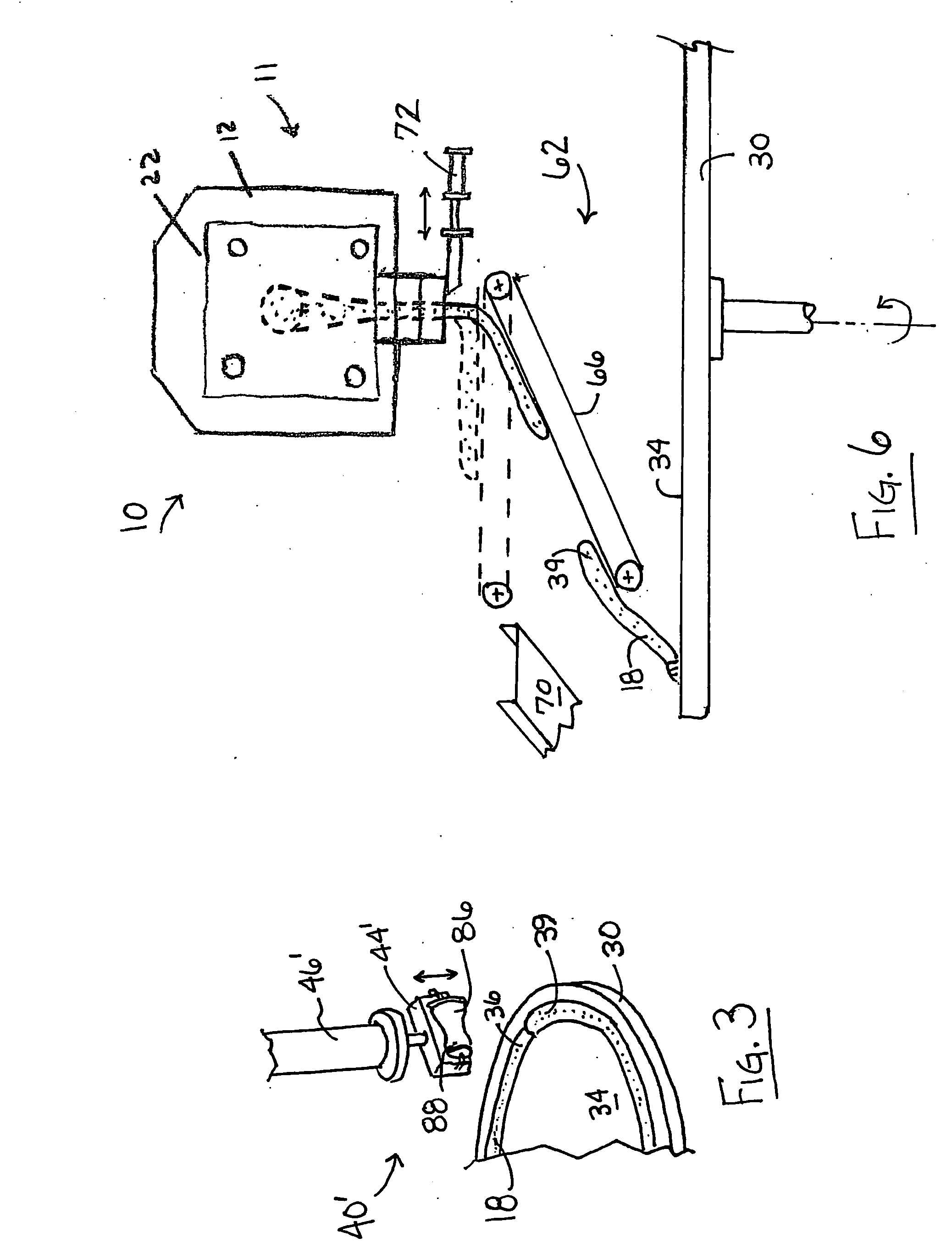
Process for forming an annular member by extruding a thermoplastic profiled strip at an elevated temperature. Prior to cooling the strip, the still-molten ends undergo in-line compression molding to form an annular member having a joint section. The cross-section of the annular member is continuous in the joint section and the remainder of the body. Preferably, the extrudate may contain a thermoplastic elastomer, more preferably a thermoplastic vulcanizate formed by a dynamic vulcanization process. During the extrusion and compression molding processes, the extrudate may be supported on a rotatable turntable, or alternately on a rotatable molding cylinder.

Description

FIELD OF INVENTION [0001] The invention generally relates to a process for forming an annular member comprising one or more thermoplastics. The annular member thus formed is particularly useful in pipe seal applications. BACKGROUND ART [0002] In applications such as pipe seals, the governing specifications require the material to have a low compression set. Thermoset rubbers (TSR), those vulcanized or cross-linked after molding, have typically been used. Thermoplastics and thermoplastic elastomers have been proposed to replace TSR in many applications, particularly dynamically vulcanized thermoplastic elastomers, e.g., thermoplastic vulcanizates (TPV). A TPV typically consists of a vulcanized rubber particle phase dispersed within a continuous thermoplastic phase. Those currently proposed to meet typical pipe seal specifications are grades having a hardness of approximately 45-65 Shore A. To form a ring member from an extruded profile, there must necessarily be a joint or weld. The ...

Claims


Application Information

Patent Timeline
IPC IPC(8): B29C65/00
CPCB29C47/0014B29C66/49B29C47/0038B29C47/004B29C47/0866B29C53/50B29C65/028B29C66/1122B29C2791/001B29D99/0085B29L2031/265B29L2031/7096B29C65/7847B29C66/4322B29C66/4324B29C47/0035B29C66/8322B29C66/71B29C66/8242B29C48/05B29C48/131B29C48/001B29C48/0011B29C48/266B29K2021/003
Inventor SMITH, JEFFREY M.PETERSON, DUANE E.SEYMOUR, HAROLD H.
Owner CELANESE INT CORP
Learn More