
Production system and production method

Active Publication Date: 2006-10-05
SEMICON ENERGY LAB CO LTD
View PDF48 Cites 6 Cited by
  • Summary
  • Abstract
  • Description
  • Claims
  • Application Information

AI Technical Summary

Benefits of technology

[0004] In the case of increasing demand steadily, it is easy for producers to accomplish to balance shortening of delivery date to customers and reduction of manufacturing cost by introducing make-to-stock production. However in the case of products having a short life-cycle such as electric apparatuses, which are replaced with new products for about several months to half a year to promote demand, it is extremely difficult to make a production planning for a medium and long term. Further, today when innovation of technology is fast, there is a risk in which obsolescence of products proceeds rapidly. As simple make-to-stock production, there is possibility in which a large quantity of dead stocks is left when demand declines rapidly.
[0005] In views of these conditions, it is an object of the present invention to provide a production system and a production method, which can change a period to delivery of products flexibly depending on changing of demand, in the case of producing a plurality of products having different specifications by mixing.
[0014] In accordance with the present invention, a production line, in which a process that can be applied common to production of a plurality of products is provided in an upper process, and a process that is compatible with a unique process in the production of the plurality of productions is arranged in a lower process, is designed. Therefore, productivity can be increased. In other words, volume of production can be adjusted flexibly depending on demand of each product. Therefore, a production corresponding to a demand from customers can be performed without increasing dead stocks or intermediate dead stocks. Further, when demand is inclined to one kind, production can be performed in a state of keeping driving rate of a manufacturing device a fixed quantity to reduce a break-even point.

Problems solved by technology

However in the case of products having a short life-cycle such as electric apparatuses, which are replaced with new products for about several months to half a year to promote demand, it is extremely difficult to make a production planning for a medium and long term.
Further, today when innovation of technology is fast, there is a risk in which obsolescence of products proceeds rapidly.
As simple make-to-stock production, there is possibility in which a large quantity of dead stocks is left when demand declines rapidly.

Method used


Image

  • Production system and production method
  • Production system and production method
  • Production system and production method

Examples


embodiment 1

[0080] In the present embodiment, one example of producing different kinds of display devices over a same production line will be described. A display device manufactured here forms a display screen by arranging pixels in a matrix. As a specific example, a case of producing a liquid crystal display device and an EL display device is shown.

[0081] The liquid crystal display device displays a picture by utilizing electro-optic characteristics of a liquid crystal by corresponding to an electric signal that is applied to a pixel. The EL display device displays a picture by utilizing a change of luminance from emission of light and non-emission of light of a light emitting element forming a pixel.

[0082] In the present embodiment, the above display devices are formed by using a thin film transistor in which a channel forming region is formed by using a semiconductor film. The thin film transistor is provided in a pixel to control a signal inputted to the pixel. Further, the thin film tra...

embodiment 2

[0088] Details of a process for manufacturing a display device will be shown is based on Embodiment 1. The present embodiment illustrates a process for manufacturing a liquid crystal display device. This manufacturing process includes a process for manufacturing a thin film transistor and a process for manufacturing a liquid crystal element.

[0089]FIGS. 8A to 8C show a process (X1) for forming a semiconductor layer. This process is categorized into the upper process 101 in FIG. 6. This process for forming a semiconductor layer is described with reference to FIGS. 8A to 8C. In FIG. 8A, a blocking layer 302 and a semiconductor layer 303 are formed over a glass substrate 301. The blocking layer 302 is provided between the glass substrate 301 and the semiconductor layer 303 to prevent pollution of the semiconductor layer 303. The semiconductor layer 303 is formed by a thin film-formation method such as low pressure chemical vapor deposition (CVD), plasma CVD, or sputtering. The semicond...

embodiment 3

[0105] Details of a process for manufacturing a display device will be shown, which is based on Embodiment 1. The present embodiment illustrates a process for manufacturing an EL display device. In this manufacturing process, a process for manufacturing a thin film transistor and a process for manufacturing an EL element are included. It is to be noted that the same reference numerals are denoted in the same portion as Embodiment 2, and the description of details are omitted.

[0106] Since a process (X1) for forming a semiconductor layer is the same as that in Embodiment 2, a specific description is omitted. As described in FIGS. 8A to 8C, a surface protective film is formed over a polycrystalline semiconductor layer 303 so that a substrate with a formed semiconductor layer can be stocked. In addition, a process that will be shown below can be conducted by using the stocked substrate of the semiconductor layer is formed.

[0107]FIGS. 19A to 19C, FIGS. 20A to 20C, FIGS. 21A to 21C, and...


PUM


Abstract

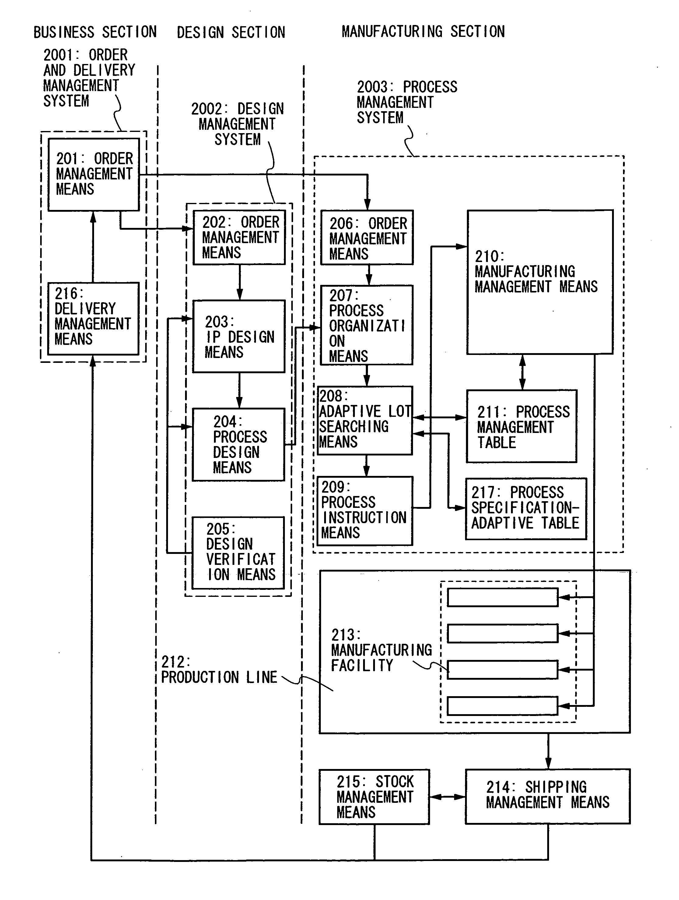
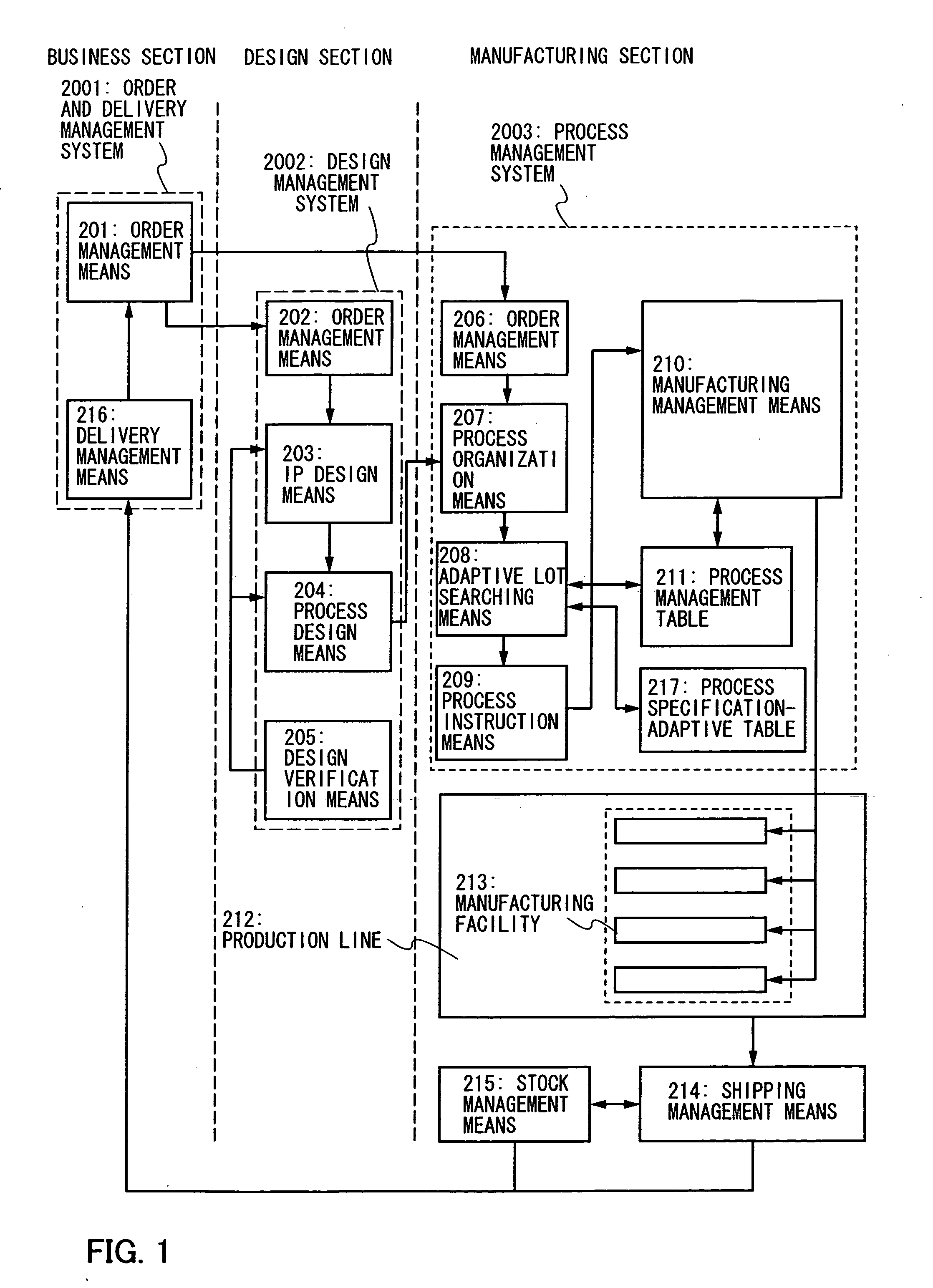
It is an object of the present invention to provide a production system and a production method, which can change a period to delivery of products flexibly depending on a change of demand, in the case of producing a plurality of products having different specifications by mixing. A production system of plural kinds of products has a plurality of lower processes, which is capable of diverging, with respect to an upper process that can be applied common in a plurality of products. These upper process and lower process are organized by including one or a plurality of processes. A production line is constructed by a plurality of manufacturing facilities having different functions through the upper process and the lower process. Such a production system is provided with an order and delivery management system, a design management system, and a process management system.

Description

BACKGROUND OF THE INVENTION [0001] The present invention relates to a production system and a production method for manufacturing a plurality of products having different specifications. The present invention relates to particularly a production system and a production method for manufacturing a plurality of products that include a plurality of processes in which there are plural lower processes, which are capable of diverging, with respect to an upper process. [0002] In order to meet diversification in the market, a limited production of diversified products method is applied in many manufacturing floors. For this method, a production system in mass production products is required to be optimized in order to achieve profit by securing a break-even point of a manufacturing line. Accordingly, measures such as optimization of stock control and sourcing, by utilizing a corporate sources planning system, has been taken (for example, see Patent Document 1). [0003] [Patent Document 1] Jap...

Claims


Application Information

Patent Timeline
IPC IPC(8): G06F19/00
CPCG06Q10/06
Inventor ARAI, YASUYUKI
Owner SEMICON ENERGY LAB CO LTD
Learn More