Non-catalytic reduction and oxidation process for the removal of NOx

a non-catalytic, oxidation technology, applied in the direction of separation processes, dispersed particle separation, chemistry apparatuses and processes, etc., can solve the problems of nosub>x /sub>emissions in total, significant fines, production slowdown or shutdown, etc., to achieve the effect of reducing nosub>x /sub>emissions

Inactive Publication Date: 2006-10-19
EXXON RES & ENG CO
View PDF27 Cites 21 Cited by
  • Summary
  • Abstract
  • Description
  • Claims
  • Application Information

AI Technical Summary

Benefits of technology

[0020] f) removing at least a fraction of said higher nitrogen oxides from said NO depleted off-gas stream to produce a treated regenerator off-gas stream.

Problems solved by technology

But since these oxidants are expensive and it is desired that they be utilized to oxide nitrogen species, the process stream must first be thoroughly pre-treated to remove all or almost all SOx prior to contacting the stream with the oxidant for NOx conversion and removal.
Although the NOx is extremely dilute in the regenerator off-gas (in the ppm range), the overall emissions of NOx are considerable due to the high volumetric flow rate of the FCC unit off-gas stream.
NOx species are regulated pollutants by the United States Environmental Protection Agency (“EPA”) and failure to meet the EPA's industrial emissions regulations can result in significant fines, or even production slowdowns or shutdowns in order to remain within regulatory compliance.
While conventional wet scrubbing is effective for reducing SOx emissions, it is not effective for reducing NOx emissions.
The NO in the off-gas stream is particularly difficult to remove without first converting the NO to elemental nitrogen or higher oxide species.
However, it is difficult to burn the carbon deposits from a spent catalyst without generating NOx in the off-gas.
It is difficult to reduce the NOx concentrations in the regenerator off-gas stream by thermal means, partially because of the low temperatures of the off-gas.
One problem that exists in the art is that non-catalytic, ammonia (NH3) based NOx reduction processes, such as disclosed U.S. Pat. No. 3,900,554 to Lyon, can result in significant amounts of ammonia in the treated gas stream.
This can result in excessive ammonia emissions and in certain applications, as in an FCCU, a significant portion of the unreacted ammonia converts into ammonium salts which can be corrosive and which tend to deposit on related downstream equipment, such as heat exchange equipment, turbines, scrubber slurry lines, environmental analyzer sample systems, etc.
These corrosive and restrictive salt deposits can cause significant equipment deterioration and system malfunctions and / or failures.
Additionally, if excess NH3 is utilized in these processes (resulting in “ammonia slip”), the NH3 reaching downstream combustion equipment will oxidize to NOx, decreasing the net NOx reduction achievable via these processes.
A problem with practicing the processes existing in the art is the inability to simultaneously achieve both high levels of NO reduction and low levels of downstream unreacted ammonia concentrations, particularly at low NO concentrations in the off-gas.
However, the many of the conventional methods involve either chemicals that require extended reaction periods or can create ancillary problems within the processing unit.
Such problems include, for example, corrosion of materials of construction, problems with treating the waste water from the unit, as well as problems relating to the removal of SOx species that are typically also present.
However, the addition of sodium chlorite to the scrubber liquor has its disadvantages.
For example, sodium chlorite is a costly chemical and can be consumed by side reactions, such as the oxidation of SOx species to higher sulfur oxides (e.g., SO32− to SO42−).
Thus, because sodium chlorite does not selectively oxidize lower oxide NOx species to higher oxides, conventional methods require the use of relatively high sodium chlorite concentrations in the scrubber liquor to achieve the desired absorption removal of oxidizable NOx species.
These high levels of sodium chlorite lead to high chloride levels that cause, among other things, corrosion of the scrubber's materials of construction.
In addition, maintaining high levels of sodium chlorite may not be financially attractive.
Another problem in the art is the lack of an effective and cost-efficient absorption solution for removing the converted NO2 from the FCC regenerator off-gas stream.
Final wash systems in the art, comprised of water and / or alkali solution such as described in United States Patent Application Number US 2004 / 0214187 A1 to Johnson et al., are relatively ineffective for removal of NO2, especially at NO2 concentrations below about 100 ppmv.
This includes the need in the industry for a process that is effective, efficient, and economic to remove NOx within restrictions of existing facilities which have limited control over the size of the off-gas treating equipment (e.g., the wet gas scrubber) and are not able to perform adequate removal of entrained sulfite-laden water droplets from the first SOx reaction zone to allow the processes of the prior art to convert and remove the NOx in the regenerator off-gas to the efficiencies required by current and future environmental emissions restrictions.

Method used


Image

  • Non-catalytic reduction and oxidation process for the removal of NOx
  • Non-catalytic reduction and oxidation process for the removal of NOx
  • Non-catalytic reduction and oxidation process for the removal of NOx

Examples


example 1

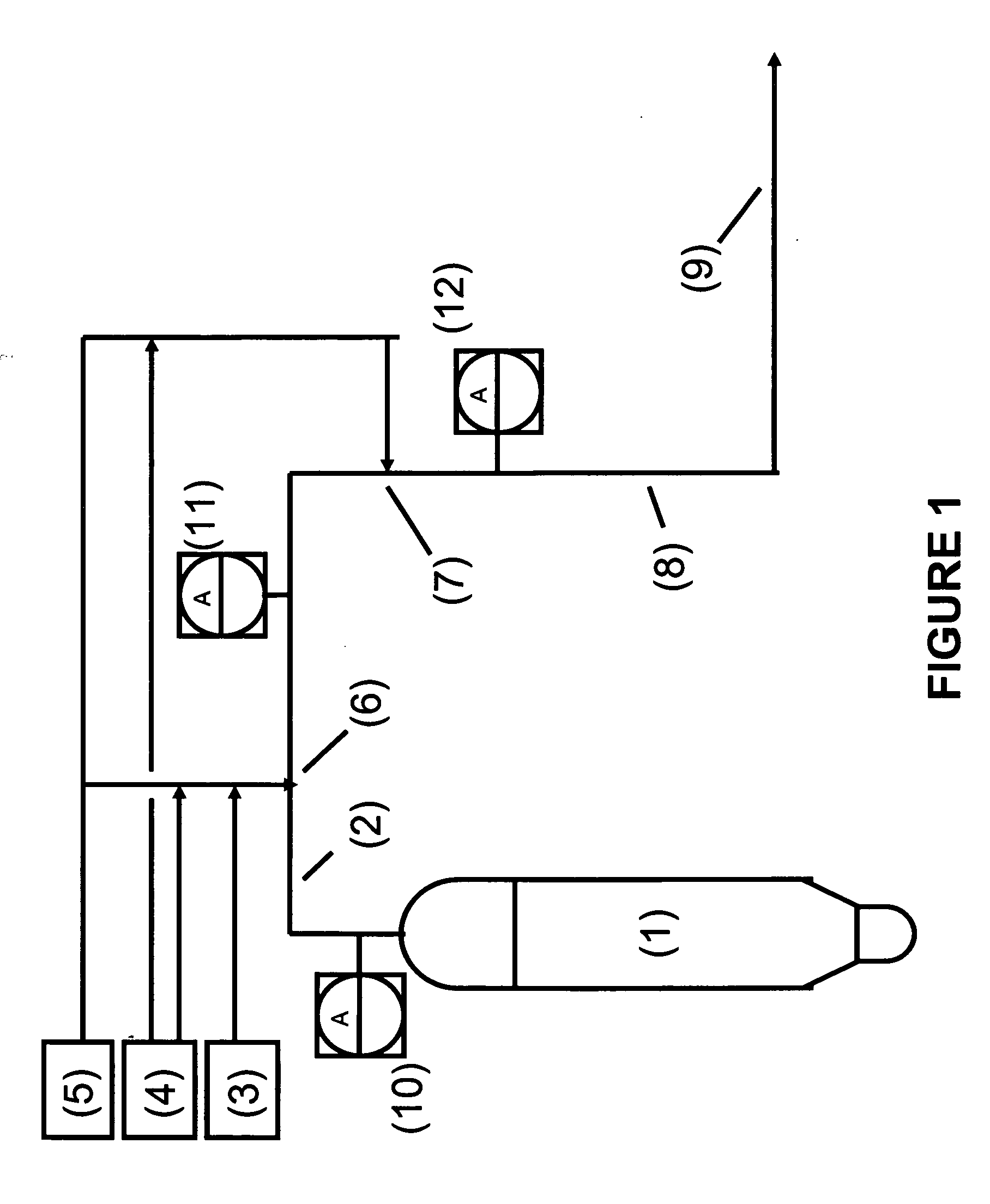
[0117] In this example, an embodiment of the reduction stage of the present invention was tested at a commercial FCCU under normal operating conditions. The configuration of the two injection points and major equipment was as shown in FIG. 1 with the exception that an intermediate analyzer (shown in FIG. 1 as element (18)) was not installed. Therefore, the remaining unreacted NH3 after the first injection point was not measured directly, but was based on calculations from “ammonia slip” data compiled when operating the regenerator off-gas NOx treatment configuration without the second injection point.

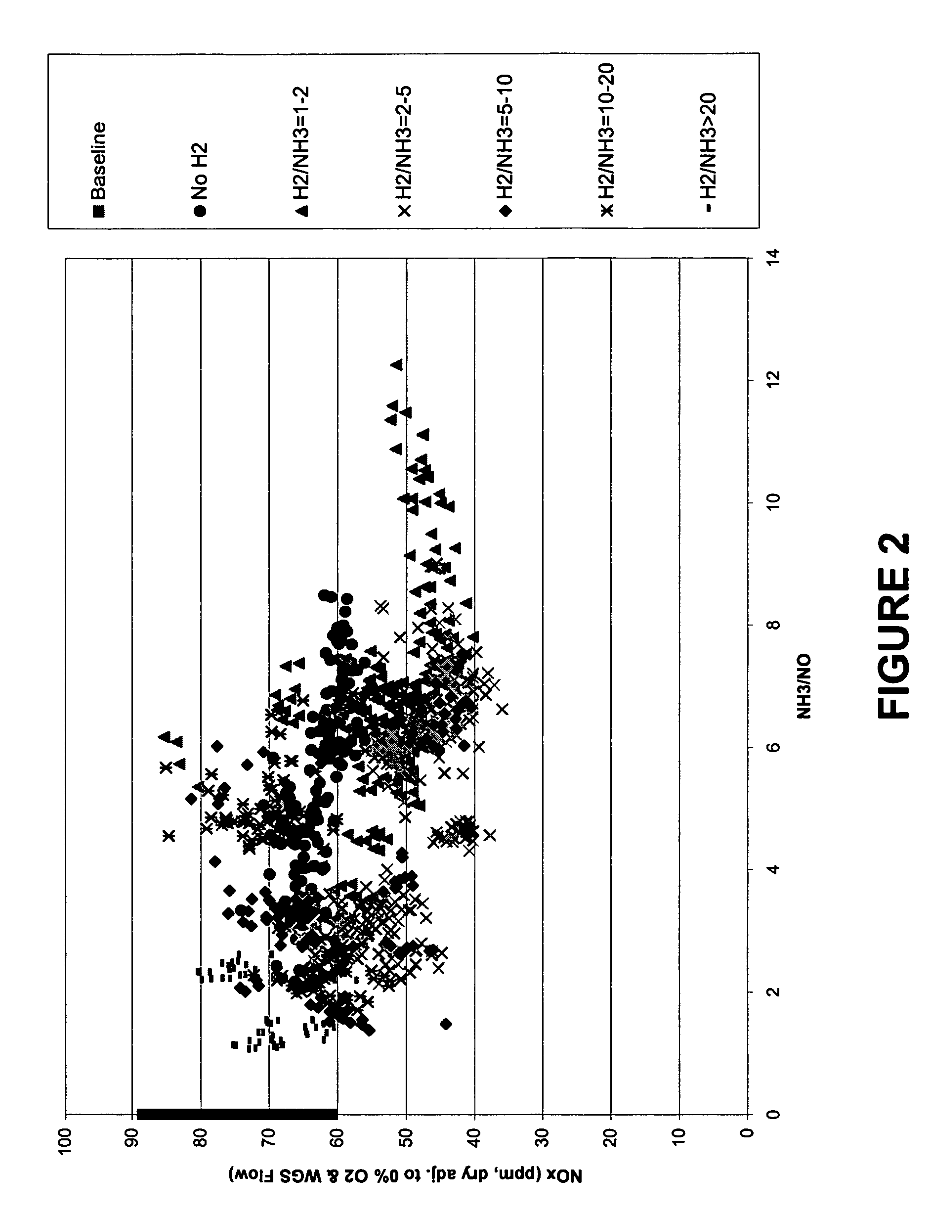
[0118] In this example, the NOx reduction configuration for the FCCU regenerator off-gas was tested with only a single injection point injecting different ratios of a reducing agent (in this case NH3) and a readily-oxidizable gas (in this case H2). This first point injection point is shown in FIG. 1 as point (6). In this example, the second injection point (7) was not utilized.

[0119] ...

example 2

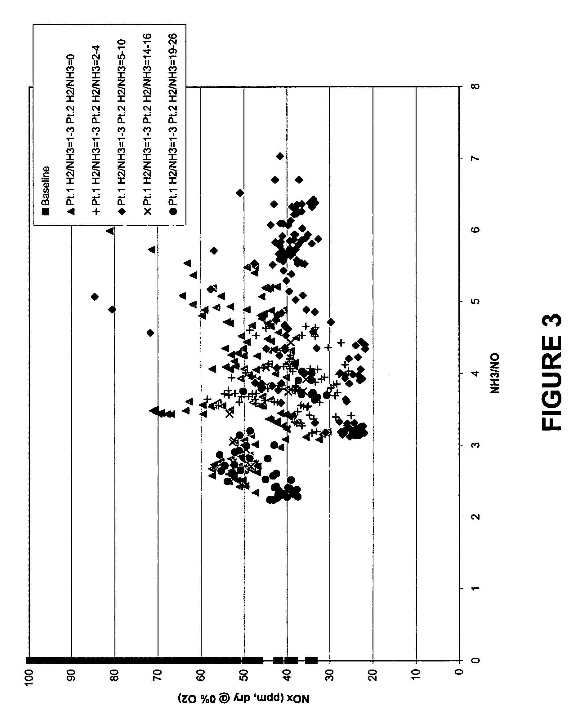
[0121] In this example, an embodiment of the reduction stage of the present invention was tested at a commercial FCCU under normal operating conditions. The configuration of the two injection points and major equipment was as shown in FIG. 1 with the exception that an intermediate analyzer (shown in FIG. 1 as element (18)) was not installed. Therefore, the remaining unreacted NH3 after the first injection point was not measured directly, but was based on calculations from “ammonia slip” data compiled when operating the regenerator off-gas NOx treatment configuration without the second injection point. This configuration is similar as to as tested in Example 1.

[0122] In this embodiment of the present invention, the NOx reduction configuration for the FCCU regenerator off-gas was tested with a two-injection point system. A molar ratio of a reducing agent (in this case NH3) to a readily-oxidizable gas (in this case H2) of 1 to 3 was injected at the first injection point. At the second...

example 3

[0127] In this example, an embodiment of the oxidation / absorption stage of the present invention was tested on a commercial FCC unit regenerator off-gas stream. A regenerator off-gas stream with an approximate flow rate of 400,000 scfm was treated in accordance with the process of the present invention. A stream comprised of water, sodium chlorite (25% concentration NaClO2 by weight), and sodium hypochlorite (12.5% concentration NaClO by weight) was introduced into the lower spray header above the lower contacting grid of the wet gas scrubber vessel at various volumetric injection levels. In this example, at the beginning of the test, only water and sodium chlorite (i.e., no sodium hypochlorite) was injected into the off-gas stream. This was followed by various levels of combined injections of sodium chlorite and sodium hypochlorite.

[0128] The overall test was run for approximately 5 hours (from 14:10 hours to 19:00 hours, see FIG. 10) and the results of the data are shown graphica...


PUM

PropertyMeasurementUnit
temperatureaaaaaaaaaa
temperaturesaaaaaaaaaa

Abstract

The present invention relates to a non-catalytic process for reducing NOx concentrations in the regenerator off-gas stream of a fluid catalytic cracking unit. More particularly, the present invention relates to the injection of a reducing agent in combination with a readily-oxidizable gas into a regenerator off-gas stream to reduce at least a portion of the NO in the regenerator off-gas stream, then contacting the regenerator off-gas stream with an effective amount of a treating solution under conditions such that at least a fraction of the oxidizable NOx species present in the regenerator off-gas stream is oxidized to higher oxides, and subsequently removing at least a fraction of these higher oxides from the off-gas stream. One embodiment of this invention also relates to the use of a reacted caustic solution from a wet gas scrubber for the removal of at least a fraction of the higher oxides.

Description

CROSS-REFERENCE TO RELATED APPLICATIONS [0001] This application is a continuation in part of U.S. patent application Ser. No. 10 / 427,223, filed May 1, 2003, and U.S. Ser. No. 10 / 427,225, filed May 1, 2003 both of which claim benefit of the following U.S. Provisional Patent Applications: Ser. No. 60 / 386,560 filed Jun. 5, 2002; Ser. No. 60 / 386,492 filed Jun. 5, 2002; and Ser. No. 60 / 442,268 filed Jan. 24, 2003.FIELD OF THE INVENTION [0002] The present invention relates to a non-catalytic process for reducing NOx concentrations in the regenerator off-gas stream of a fluid catalytic cracking unit. More particularly, the present invention relates to the injection of a reducing agent in combination with a readily-oxidizable gas into a regenerator off-gas stream to reduce at least a portion of the NO in the regenerator off-gas stream, then contacting the regenerator off-gas stream with an effective amount of a treating solution under conditions such that at least a fraction of the oxidizab...

Claims


Application Information

Patent Timeline
Patent Type & Authority Applications(United States)
IPC IPC(8): B01D53/56
CPCB01D53/502B01D53/56C10G11/182B01D2251/2062B01D2251/304B01D2251/108
Inventor BARCKHOLTZ, TIMOTHY A.HOCHHALTER, THERESA J.FABER, JOHN R.HAVRAN, CYNTHIA M.HURST, BOYD E.MCLAUGHLIN, WILLIAM J.KNIGHT, DAVID G.
Owner EXXON RES & ENG CO
Why Eureka
Try Eureka