
Nanoparticle thermometry and pressure sensors

a technology of nanoparticles and pressure sensors, applied in the direction of thermometer details, instruments, heat measurement, etc., can solve the problems of reducing the resolution of grain size, and hazardous sparks, so as to improve the resolution, reduce the cost, and the coating layer thickness

Inactive Publication Date: 2006-12-07
FLIR DETECTION
View PDF17 Cites 11 Cited by
  • Summary
  • Abstract
  • Description
  • Claims
  • Application Information

AI Technical Summary

Benefits of technology

[0011] Temperature and pressure can be determined by measuring fluorescent properties such as the intensity, the decay lifetime, or the wavelength. Using nanoparticles, particles with dimensions of less than 1000 nm, as the fluorescent material offers advantages for fluorescence-based thermometry such as higher resolution, incorporation into a variety of media, thinner coating layers, lower cost, and higher sensitivity. The energy transfer rate from a donor to an acceptor is temperature and / or pressure dependent. As a result, the luminescence from a donor-acceptor pair is sensitive to temperature and / or pressure changes. This allows one to design and fabricate an energy transfer system for temperature and / or pressure sensors, including a system composed of two sizes or two kinds of nanoparticles; or one nanoparticle or one host with two emitters. Thermometry or temperature imaging is also possible using the temperature-dependent upconversion luminescence of nanoparticles. An upconversion temperature sensor or upconversion imaging might have higher resolution and / or sensitivity because the luminescence background is much lower than in fluorescence.
[0012] Using nanoparticles for temperature sensors or nanothermometry or nanothermometers may overcome the limitations of conventional phosphors as mentioned above. Luminescent nanoparticles with high quantum efficiency make it possible to design and fabricate more sensitive temperature sensors. It is known that oscillator strength is a very important optical parameter that determines the absorption cross-section, recombination rate, luminescence efficiency, and the radiative lifetime in materials. The oscillator strength of the free exciton is given by the formula: fe⁢ ⁢x=2⁢ ⁢mη⁢Δ⁢ ⁢E⁢μ2⁢U⁡(0)2 where m is the electron mass, ΔE is the transition energy, μ is the transition dipole moment, and |U(0)|2 represents the probability of finding the electron and hole at the same site (the overlap factor). In nanostructured materials, the electron-hole overlap factor increases largely due to the quantum size confinement, thus yielding an increase in the oscillator strength. The oscillator strength is also related to the electron-hole exchange interaction that plays a key role in determining the exciton recombination rate. In bulk semiconductors, due to the extreme dislocation of the electron or hole, the electron-hole exchange interaction term is very small; while in molecular-size nanoparticles, due to the confinement, the exchange term should be very large. Therefore, one may expect a large enhancement of the oscillator strength from bulk to nanostructured materials.
[0013] In doped semiconductors, excitons are bound to impurity centers. The oscillator strength is given by the formula: f=fe⁢ ⁢x⁢∫ⅆx⁢ ⁢F⁡(x)2 / Ωm⁢ ⁢o⁢ ⁢l, where fex is the oscillator strength of the free exciton and Ωmol is the volume of one molecule. The oscillator strength of a bound exciton is actually given by fex multiplied by the number of molecules covered by the overlap of the electron and hole wave functions. Clearly, quantum size confinement will also enhance the bound exciton oscillator strength in doped nanoparticles. The luminescence efficiency is also proportional to the exciton oscillator strength; therefore, it can be enhanced via quantum size confinement. Strong evidences for the above theory are from our observations on ZnS:Mn2+ nanoparticles as reported in W. Chen, R. Sammynaiken, Y. Huang, J. Appl. Phys. Luminescence Enhancement of ZnS:Mn Nanoclusters in Zeolite, 2000, 88, 5188 (2000) and EuS, W. Chen, X. H. Zhang, Y. Huang, Luminescence Enhancement of EuS Clusters in USY-Zeolite, Appl. Phys. Lett., 76 (17): 2328-2330 (2000). The luminescence intensity of the 1 nm sized ZnS:Mn2+ nanoparticles in zeolite-Y was reported to be much stronger than other nanoparticles in W. Chen, R. Sammynaiken, Y Huang, J. Appl. Phys. Luminescence Enhancement of ZnS:Mn Nanoclusters in Zeolite, 2000, 88, 5188 (2000). More interesting is that bulk EuS at room temperature is reported as not luminescent but strong luminescence was observed when EuS nanoparticles were formed in zeolite (see W. Chen, X. H. Zhang, Y Huang, Luminescence Enhancement of EuS Clusters in USY-Zeolite, Appl. Phys. Lett., 76 (17): 2328-2330 (2000)).

Problems solved by technology

Thermistors, thermocouples, and RTDs all require electrical wiring, which is not suitable for applications in which electromagnetic noise is strong, sparks could be hazardous, the environment is corrosive, or parts are rapidly moving.
Infrared measurements have two essential flaws in sample comparison and common interferants.
The grain size limits resolution by scattering both the excitation light and emitted light.
Thick coatings are disadvantageous because the phosphor coating may act as an insulating layer on the part's surface, giving results for temperature that cannot be applied to similar uncoated parts.
This introduces a delay in making temperature measurements while the sensor comes to thermal equilibrium with what it is measuring.
There is a limited selection of materials for this approach.
The application of this kind of thermometer is focused on cryogenic temperature monitoring, and the thermometer has been found insensitive to high magnetic fields.
However, the temperature sensing only works at temperatures below 100 K.

Method used


Image

  • Nanoparticle thermometry and pressure sensors
  • Nanoparticle thermometry and pressure sensors
  • Nanoparticle thermometry and pressure sensors

Examples


example 1

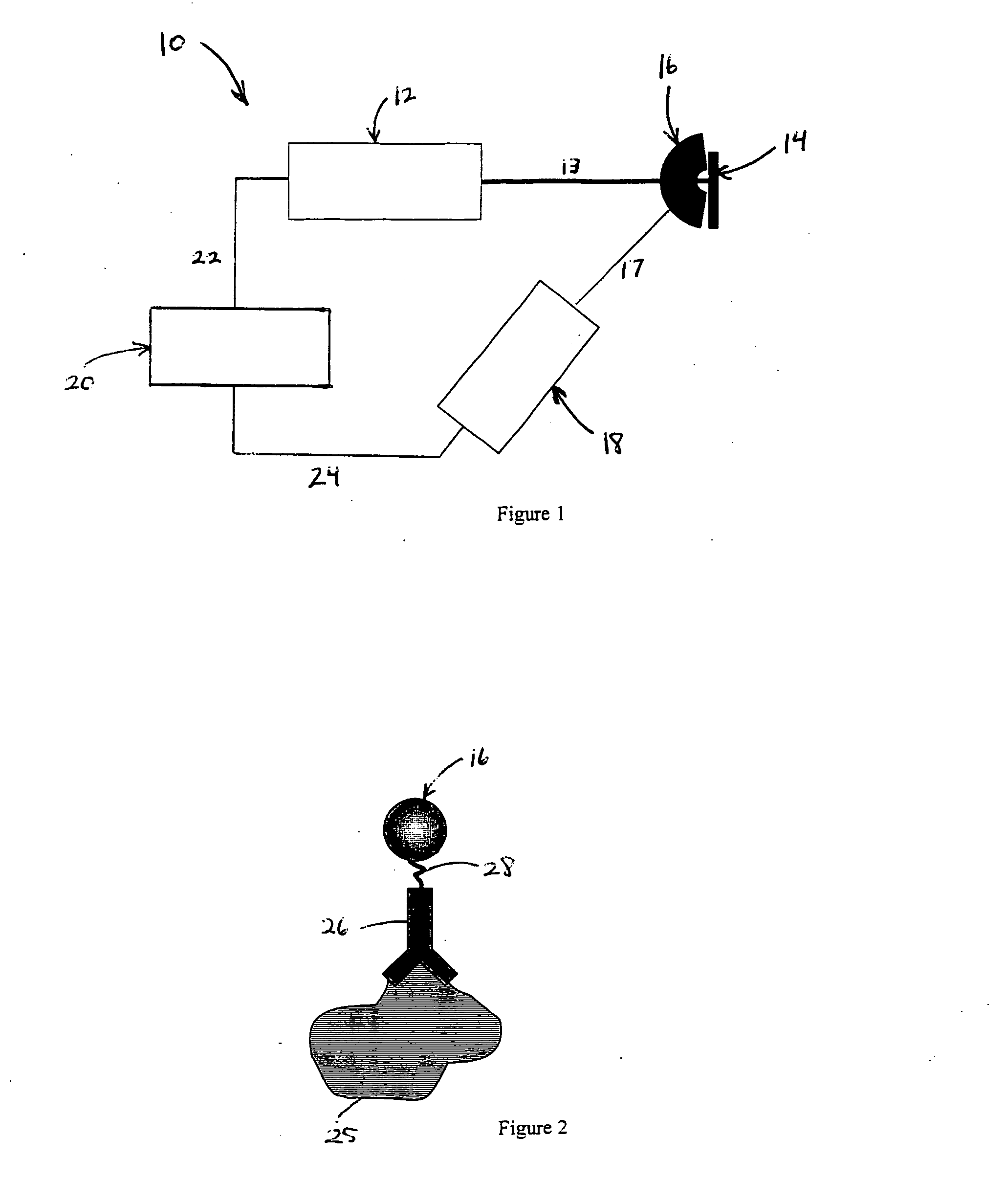
[0086] An application of nanothermometry is localized in vivo temperature probing. In the current art, polymer beads (80-90 nm in diameter) containing fluorescent molecules have been used to measure the temperature of a single living cell for disease and cancer diagnosis. However, these fluorescent molecules are susceptible to photobleaching and are not suitable for long-term monitoring. Nanoparticles are less susceptible to photobleaching, are even smaller for injection into the cell, and can be readily conjugated to biomolecules, such as antibodies, to control where they will bind (see FIG. 2). This site-specific. conjugation approach will yield nanoparticle-antibody conjugates having high binding affinity to the target.

example 2

[0087] Nanoparticle thermometry can also be used to monitor local temperature of macro molecules in vitro; one example is the hybridization and dehybridization of DNA during the polymer chain reaction (PCR) for amplification of genes, where temperature plays a key role. In the current art, an organic phosphor such as 6-carboxyfluorescein has been chemically attached to the end of DNA molecules to monitor the temperature of the DNA molecule locally, by measuring the fluorescence emission intensity. The nanoparticles disclosed herein may be used as a replacement for the organic phosphors with similar benefits as described in Example 1.

example 3

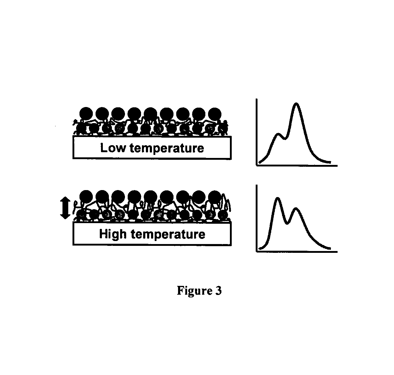
[0088] To utilize the FRET response between different nanoparticles for the thermometry application, a proper linking method needs to be selected to make the two kinds of nanoparticles close enough for FRET. The linker needs to have thermal expansion properties that will vary the FRET distance thermally. Either chemical or physical linking methods could be selected. A properly selected organic linker molecule with functional groups that can conjugate to the stabilizer on the surface of each kind of nanoparticles is one approach. The advantages of such molecular linking are strong and stable linking. A physical linking method, layer-by-layer assembly, should provide a general approach for making a FRET nanostructure.

[0089] G. Decher initially introduced layer-by-layer (LBL) assembly for oppositely charged polyelectrolytes as discussed in G. Decher, Fuzzy Nanoassemblies: toward Layered Polymeric Multicomposites, Science 277, 1232-1237 (1997), the entire content of such reference is h...


PUM

PropertyMeasurementUnit
temperaturesaaaaaaaaaa
distanceaaaaaaaaaa
excitation wavelengthaaaaaaaaaa

Abstract

A nanoparticle fluorescence (or upconversion) sensor comprises an electromagnetic source, a sample and a detector. The electromagnetic source emits an excitation. The sample is positioned within the excitation. At least a portion of the sample is associated with a sensory material. The sensory material receives at least a portion of the excitation emitted by the electromagnetic source. The sensory material has a plurality of luminescent nanoparticles luminescing upon receipt of the excitation with luminance emitted by the luminescent nanoparticles changing based on at least one of temperature and pressure. The detector receives at least a portion of the luminance emitted by the luminescent nanoparticles and outputs a luminance signal indicative of such luminance. The luminescence signal is correlated into a signal indicative of the atmosphere adjacent to the sensory material.

Description

CROSS REFERENCE TO RELATED APPLICATION [0001] The present patent application claims priority to the provisional patent application identified by U.S. Ser. No. 60 / 388,211 filed Jun. 12, 2002.BACKGROUND OF INVENTION [0002] Temperature is a fundamental property and its measurement is often required for both scientific research and industrial applications. For industrial manufacturing, real-time temperature monitoring can be used to optimize processing, minimizing waste and energy consumption. Spatially resolved temperature monitoring can establish regions of an integrated circuit in which heat builds up and suggest improvements in design of the circuit or its cooling system. Monitoring the temperature of high speed moving parts, such as turbine blades, can identify changes that signify a developing weakness in the blade. In bioengineering and biochemistry, temperature changes of even a few degrees can mean the difference between life and death for a cell. [0003] Traditional methods of ...

Claims


Application Information

Patent Timeline
Patent Type & Authority Applications(United States)
IPC IPC(8): G01K11/00G01K13/00G01K1/14G01K11/20G01K11/32
CPCG01K11/20G01K2211/00G01K11/3213
Inventor CHEN, WEIWANG, SHAOPENGWESTCOTT, SARAH
Owner FLIR DETECTION
Learn More