Organic element for low voltage electroluminescent devices
- Summary
- Abstract
- Description
- Claims
- Application Information
AI Technical Summary
Benefits of technology
Problems solved by technology
Method used
Image

Examples
example 1a
Synthesis of Cpd-2
[0231]
[0232] Compound (3), eq. 1, was prepared in the following manner. Under a nitrogen atmosphere, acetylenic compound (2) (2.0 g, 12 mMole), was dissolved in dimethylformamide (DMF) (100 mL) and the solution cool to 0° C. Potassium t-butoxide (KButO) (1.4 g, 12 mMole), was added and the mixture stirred well for approximately 15 minutes. To this mixture was then added the benzophenone (1) (3.53 g, 30 mMole). Stirring was continued at 0° C. for approximately 30 minutes and then allowed to come to room temperature over a 1-hour period. At the end of this time the solution was cooled to 0° C. and the reaction treated with saturated sodium chloride (20 mL). The mixture was then diluted with ethyl acetate, washed with 2N—HCl (3 times), dried over MgSO4, filtered and concentrated under reduced pressure. The crude product was triturated with petroleum ether to give the product as an off-white solid. The yield of compound (3) was 3.0 g.
[0233] Compound (3) (7.0 g, 15 mMo...
example 1b
Synthesis of MC-1
[0234]
[0235] 8-Hydroxyquinoline (4.64 g, 31.96 mMoles) was dissolved in acetonitrile (50 mL). To this solution was added 2.5M n-BuLi (15.5 mL, 36.36 mMoles) drop by drop at room temperature under a nitrogen atmosphere. After the addition of the n-BuLi, the mixture was stirred for 1 hour. The yellow solid was filtered off, washed with a little cold water, acetonitrile and finally air dried. The yield of lithium 8-quinolate (Liq) was 4.8 g.
example 2
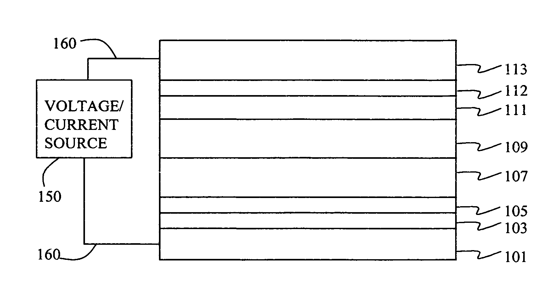
Preparation of Devices 1-1 Through 1-6
[0236] A series of EL devices (1-1 through 1-6) were constructed in the following manner. [0237] 1. A glass substrate coated with an 85 nm layer of indium-tin oxide (ITO), as the anode, was sequentially ultrasonicated in a commercial detergent, rinsed in deionized water, degreased in toluene vapor and exposed to oxygen plasma for about 1 min. [0238] 2. Over the ITO was deposited a 1 nm fluorocarbon (CFx) hole-injecting layer (HIL) by plasma-assisted deposition of CHF3 as described in U.S. Pat. No. 6,208,075. [0239] 3. Next a layer of hole-transporting material 4,4′-Bis[N-(1-naphthyl)-N-phenylamino]biphenyl (NPB) was deposited to a thickness of 75 nm. [0240] 4. A 35 nm light-emitting layer (LEL) corresponding to the host material rubrene and 0.5% by volume of L46 was then deposited. [0241] 5. A 35 nm electron-transporting layer (ETL) of MC-3 or Cpd-1 (Rubrene) or a mixture of the two (see Table 1) was vacuum-deposited over the LEL. [0242] 6. 0.5...
PUM
| Property | Measurement | Unit |
|---|---|---|
| Fraction | aaaaa | aaaaa |
| Fraction | aaaaa | aaaaa |
| Fraction | aaaaa | aaaaa |
Abstract
Description
Claims
Application Information
 - Generate Ideas
- Intellectual Property
- Life Sciences
- Materials
- Tech Scout
- Unparalleled Data Quality
- Higher Quality Content
- 60% Fewer Hallucinations
Browse by: Latest US Patents, China's latest patents, Technical Efficacy Thesaurus, Application Domain, Technology Topic, Popular Technical Reports.
© 2025 PatSnap. All rights reserved.Legal|Privacy policy|Modern Slavery Act Transparency Statement|Sitemap|About US| Contact US: help@patsnap.com