Analytical system and method for analyzing nonlinear optical signals

Inactive Publication Date: 2006-12-28
BAYER TECH SERVICES GMBH +1
View PDF29 Cites 17 Cited by
  • Summary
  • Abstract
  • Description
  • Claims
  • Application Information

AI Technical Summary

Benefits of technology

[0044] A multiplicity of possible embodiments of the method according to the invention are distinguished by the fact that the modulation of the excitation light radiated in to an interaction space is effected by means of optomechanical and/or acousto-optical and/or electro-optically active auxiliary means.
[0045] Said optomechanical and/or acousto-optical and/or electro-optically active auxiliary means may be selected from the group comprising mechanical shutters (comparable to camera shutters) and rotating choppers which in each case alternately block and release the light path between the excitation light source and the interaction space, polarization-selective components such as, for example, rotating half-wave plates in combination with polarizers, liquid crystal attenuators, electro-optically active crystals, neutral density filters that are locally or temporally variable in terms of their transmission, acousto-optical modulators and also modulators based on interference effects, such as, for example, Michelson interferometers or Mach-cylinder interferometers.
[0046] What is characteristic of other embodiments of the method according to the invention is that the modulation of the excitation light radiated in to an interaction space is effected by means of direct, active modulation

Problems solved by technology

One disadvantage of the method for detecting luminescence excited in evanescent fashion as described previously in the prior art, in particular in WO 95/33197 and WO 95/33198, is that in each case only one sample is analyzed by means of the embodiments of sensor platforms described therein.
In order to be able to carry out further measurements on the same sensor platform, complicated washing or cleaning steps are continuously required.
However, dividing the sensor platform into separate wave-guiding regions disadvantageously has the consequence that the space requirement for discrete measurement regions, in discrete wave-guiding regions on the common sensor platform is relatively large and, therefore, it is again possible to achieve only a comparatively low density of different measurement zones (or so-called “features”).
However, this results in a longer expenditure of time for the read-out of a large array and a relatively complex optical construction.
For all of the configurations mentioned, however, ultimately primarily the background signals and the associated background noise remain limiting factors for the detection limits that can respectively be achieved.
Although some luminescent dyes are known which have a large Stokes Shift, up to approximately 300 nm, such as some lanthanide complexes, for example, these disadvantageously generally have a relatively low quantum efficiency and/or low photostability.
Moreover, in the case of the known arrangements based on thin-film waveguides having a high refractive index, for example based on wave-guiding layers made of Ta2O5 or TiO2, with conventional excitation, it is disadvantageous that the propagation losses of these waveguides and also the intrinsic fluorescence of these thin-film waveguides (for example through traces of fluorescent contaminants in the c

Method used


Image

  • Analytical system and method for analyzing nonlinear optical signals
  • Analytical system and method for analyzing nonlinear optical signals
  • Analytical system and method for analyzing nonlinear optical signals

Examples


examples

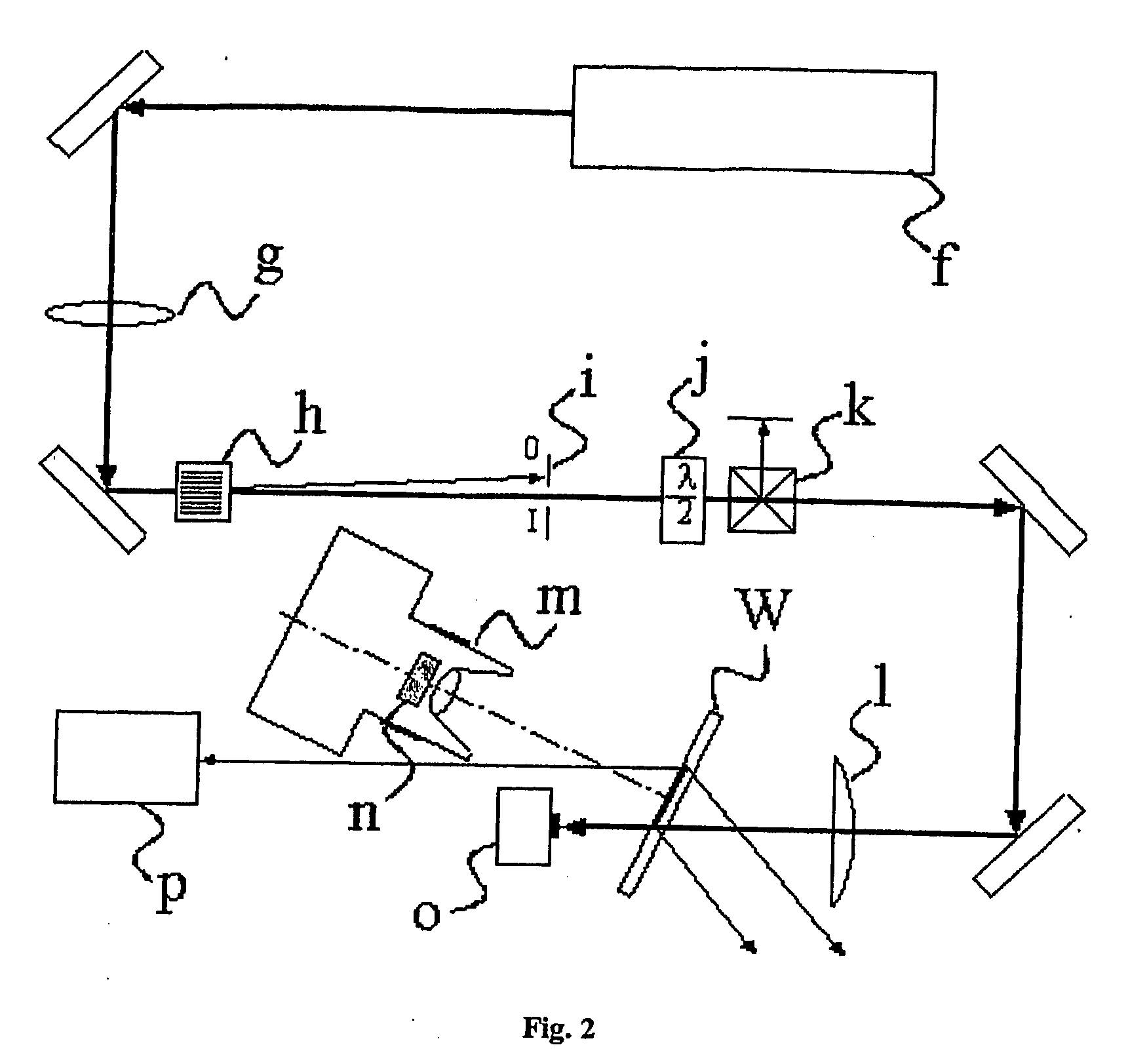
[0096] An analytical system according to the invention comprises an interaction space in accordance with the abovementioned definition, in which it is possible to generate response signals that are correlated nonlinearly with variations of an excitation light radiated in, an optical system for the excitation and detection (by means of a one- or two-dimensional detector array) of said response signals, a computer to which the detector signals are transmitted and stored in a data matrix and with the aid of which the measurement data are then split—according to a specification according to the invention—into their portions that are differently correlated with the excitation light.

[0097] A method according to the invention comprises the use of an analytical system according to the invention for generating and detecting response signals that are correlated nonlinearly with an excitation light in an interaction volume as defined above, and the splitting of the recorded measurement data a...


PUM


Abstract

The invention relates to a method for the ultrasensitive simultaneous measurement of nonlinear optical emission signals in one or two local dimensions. Said method comprises the following steps: the excitation light is irradiated in a power-modulated or pulse-modulated form from at least one light source into an interactive volume or onto an interactive area or layer (hereafter called interactive spaces) in which one or several emissions that are nonlinearly correlated with the excitement light can be excited; the light emanating from said interactive spaces is measured by means of a one-dimensional or two-dimensional detector array; the measured data is transmitted from said detector array to a computer, and said data is formatted in a one-dimensional or two-dimensional data matrix. The inventive method is characterized in that non-correlated portions of the light emanating from the interactive spaces or the portions thereof that are linearly proportionate to the intensity of the excitement light available in said interactive spaces are separated from portions of the light emanating from the interactive spaces, which are not linearly proportionate to the intensity of the available excitement light. The invention further relates to an analytical system that is suitable for carrying out the inventive method.

Description

[0001] The present invention describes a method for detecting optical signals on which scattered, noise and background signals, for example, are superposed. Specifically, this method is suitable for detecting weak nonlinear optical signals, such as, for example, of luminescence after two-photon excitation, that is to say after simultaneous absorption of two photons having a relatively low energy (relatively long wavelength) by a chromophore capable of luminescence, which leads to the emission of a photon having a higher energy (shorter wavelength) than that of the excitation light in the form of luminescence [W. Denk, J. H. Strickler and W. W. Webb, “Two-photon laser scanning fluorescence microscopy”, Science 248 (1990) 73-76; Duveneck, G. L. et al., “Evanescent-field-induced two-photon fluorescence: excitation of macroscopic areas of planar waveguides”, Applied Physics B, 73 (2001) 869-871.][0002] Nonlinear optical signals are characterized in that their signal magnitudes depend no...

Claims


Application Information

Patent Timeline
IPC IPC(8): G02B6/26G01N21/64G01N33/543
CPCG01N21/6428G01N21/648G01N21/6456G01N21/6452
Inventor HAIML, MARKUSBALET, LAURENT P.DUVENECK, GERT L.MAROWSKY, GERD
Owner BAYER TECH SERVICES GMBH
Why Eureka
Try Eureka