Removal of arsenic from water with oxidized metal coated pumice

Inactive Publication Date: 2007-01-25
BOARD OF RGT THE UNIV OF TEXAS SYST
View PDF22 Cites 44 Cited by
  • Summary
  • Abstract
  • Description
  • Claims
  • Application Information

AI Technical Summary

Benefits of technology

[0030] It is envisioned that disposal of the spent oxidized metal coated pumice could comprise burying it in a landfill. Since the As remains tightly

Problems solved by technology
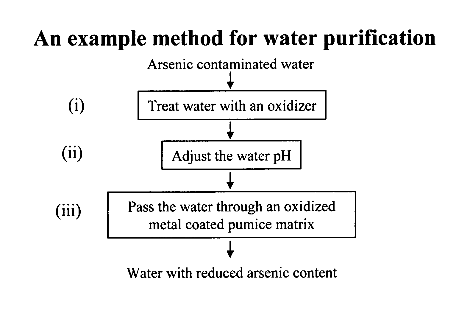
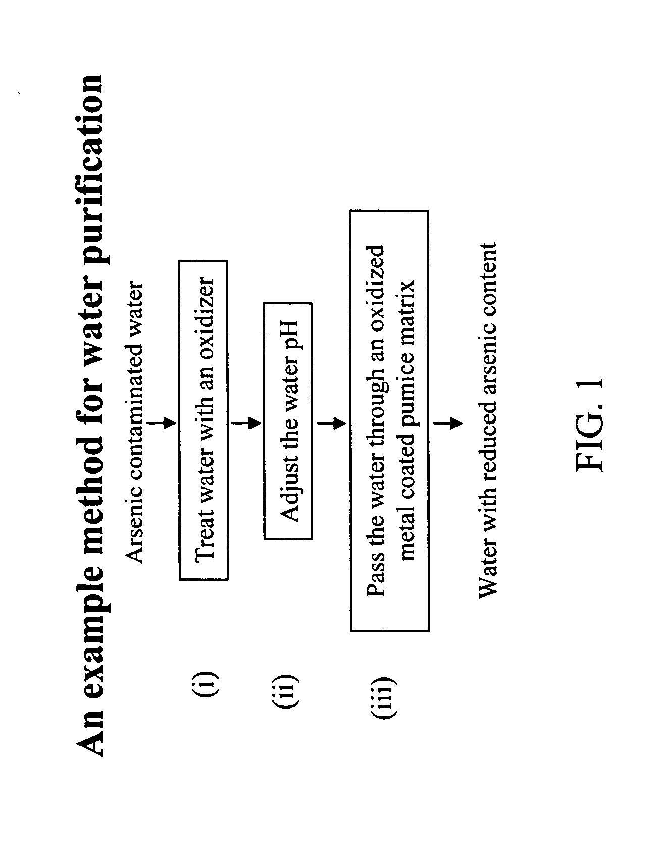
Though these methods are effective for As removal their complexity and cost precludes their implementation in rural areas and developing countries.
However, these meth

Method used


Image

  • Removal of arsenic from water with oxidized metal coated pumice
  • Removal of arsenic from water with oxidized metal coated pumice
  • Removal of arsenic from water with oxidized metal coated pumice

Examples


example 1

Coating Pumice with Iron Hydroxide

[0069] Natural pumice stones were broken into aggregate size US Sieve Size No. 18×20 and coated with iron hydroxide by the procedure similar to that of Joshi and Chaudhuri (1996). The procedure comprised pre-washing of pumice stone by immersing in deionized (DI) water for 24 hours, drying them in an oven at 105° C. for 14 hours. After drying, pumice stones were saturated with 2M ferric nitrate (2M Fe(NO3)3.9H2O), prepared by dissolving 808 g Fe(NO3)3.9H2O in DI water and diluting to 1000 ml. The pH of the mixture was adjusted to 11 with ION sodium hydroxide solution. The mixture was mixed for two minutes and dried in an oven at 110° C. for 14 hours. The coated Pumice Stone was washed with distilled water and the runoff was removed, the material was dried in an oven at 105° C. for 14 hours, and stored in a plastic bottle.

example 2

Screening Material for As Removal

[0070] Several materials have been examined for arsenic removal by adsorption. The materials selected for screening test were natural pumice stone, pumice stone coated with oxidized iron, natural zeolite, zeolite coated with oxidized iron, black sand, red sand, red soil, iron slag, red shale, hematite, copper slag, and natural garnet.

[0071] Initially, indicated concentrations of adsorbent materials were placed in individual batch reactors (plastic bottles) containing arsenic (V)(Na2HAsO4.7H2O) spiked water. The concentration of the As (V) in the water was 100 μg / L. The pH of the water was about 6 and the temperature was 250° C. The slurry was agitated with a mechanical shaker for 12 hours to give adequate contact between the adsorbent and dissolved arsenic (V). After sufficient contact time, water samples from each reactor were drawn and analyzed for total arsenic. The laboratory results and other relevant data for screening test are presented in T...

example 3

Screening Candidate Material for As Removal

[0073] Pumice stone, zeolite, and sand each coated with oxidized iron were selected for further testing. The black sand was coated with ferric nitrate by the procedure similar to that of Joshi and Chaudhuri (1996). The abosrbtion of each material was evaluated in batch reactions. Initially 0.2, 1.0, 2.0, and in some cases 2.8 grams of adsorbent material was weighed and transferred into individual batch reactors (plastic bottles) containing 1000 ml arsenic spiked water (100 (μg / L)). The slurry was agitated with a mechanical shaker for 14 hours to obtain adequate contact between the arsenic in water and the adsorbents. After sufficient contact time, samples were drawn, filtered, preserved with nitric acid, and delivered to the laboratory for analysis for arsenic. The results for batch tests are shown in Table 3 and FIG. 4.

[0074] As presented in the Table 3, 2.0 g / L of coated pumice stone adsorbed 98% detectable arsenic (V) (Na2HAsO40.7H2O) ...


PUM

PropertyMeasurementUnit
Temperatureaaaaaaaaaa
Densityaaaaaaaaaa
Dimensionless propertyaaaaaaaaaa

Abstract

The current invention is concerned with methods and compositions for the removal of arsenic contamination from water. A method for binding As to oxidized metal coated pumice and method for making the same are disclosed. Water filters comprising oxidized metal coated pumice, such as oxidized iron coated pumice, are also provided.

Description

[0001] This application claims priority to U.S. Provisional Patent application Ser. No. 60 / 680,920 filed May 13, 2005, which is incorporated by reference in its entirety.BACKGROUND OF THE INVENTION [0002] 1. Field of the Invention [0003] The invention relates generally to the field of chemistry. In particular the invention involves compositions and methods that may be used in water purification. [0004] 2. Description of Related Art [0005] Arsenic is a naturally-occurring element in the surface and subsurface environment that ranks 20th in abundance in the earth's crust. Arsenic is present at very low concentrations in rocks and soils, which are the prime sources of arsenic in ground water. However, some arsenic in ground water is likely leached from sulfide minerals within bedrock and transported to aquifers. Sulfide minerals, in particular, are known to contain high concentrations of arsenic. [0006] Arsenic in water occurs in two valance states, arsenite (As III) and arsenate (As V...

Claims


Application Information

Patent Timeline
IPC IPC(8): C02F1/42
CPCB01J20/0229B01J2220/60B01J20/10B01J20/3236C02F1/281C02F1/288C02F1/66C02F1/72C02F1/722C02F1/76C02F1/78C02F2101/103B01J20/3204B01J2220/58B01J20/06
Inventor REDDY, PRATAP G.TURNER, CHARLES D.
Owner BOARD OF RGT THE UNIV OF TEXAS SYST
Why Eureka
Try Eureka